
Description
Product Overview
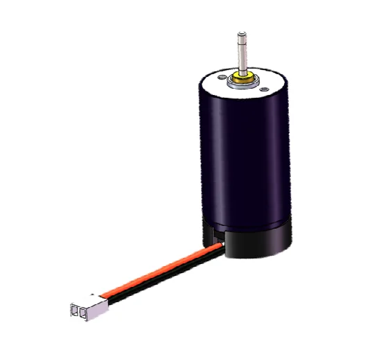
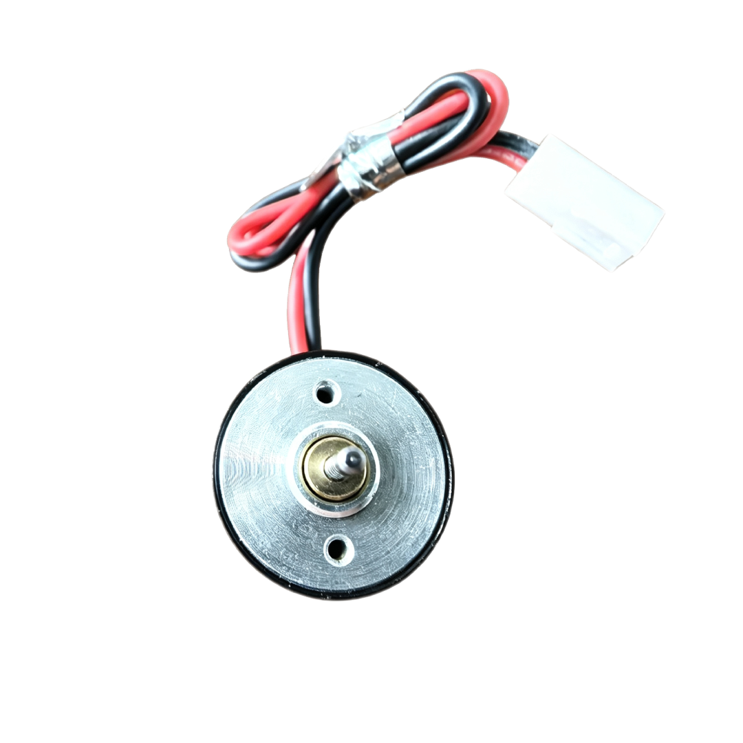
The 16SYYK30D06-N01 uses brushes and a commutator to direct current through its rotating winding. The winding interacts with the permanent magnetic field to generate torque and turn the output shaft.
The coreless rotor contains no iron core within the rotating winding assembly. Its comparatively low inertia can support a rapid response to drive commands, depending on the attached load and available current.
The motor can operate as part of a direct rotary drive or connect to a compatible transmission. The equipment’s torque, speed, and positioning requirements determine the appropriate arrangement.
Key Features
Coreless Winding Structure
The self-supporting rotor winding removes the rotating iron core found in conventional iron-core designs. This construction reduces rotor inertia and eliminates cogging caused by rotor teeth interacting with the magnetic field.
Responsive Starting and Speed Changes
Low rotor inertia helps the motor respond to changes in electrical input. Actual acceleration depends on the controller, current availability, and inertia of the connected mechanism.
Brushed DC Commutation
Brushes and a commutator perform the switching needed to sustain rotation. This allows operation from a suitable DC supply without an electronic commutation system.
Controller-Based Speed Adjustment
A compatible motor controller can adjust speed to suit the operating sequence. Applications requiring consistent speed under varying loads may benefit from feedback control.
Integration with Mechanical Assemblies
The output shaft provides a connection point for a matching coupling or transmission. Correct alignment and suitable load support help maintain the intended operating behavior.
| Parameter | Unit | Specification |
|---|---|---|
| Rated Voltage | V DC | 6 |
| No-Load Speed | rpm | 10000 |
| No-Load Current | A | 0.035 |
| Speed Constant | rpm/V | 1667 |
| Rated Current | A | 0.060 |
| Rated Speed | rpm | 6200 |
| Rated Torque | mN·m | 0.34 |
| Stall Current | A | 0.69 |
| Stall Torque | mN·m | 3.97 |
| Maximum Efficiency | % | 75 |
| Terminal Resistance | Ω | 7.8 |
| Ambient Temperature | °C | −20 to +60 |
| Maximum Permissible Winding Temperature | °C | +80 |
| Noise Level | dB | ≤35 |
| Parameter | Specification |
|---|---|
| Brush Type | Precious Metal Brushes |
| Bearing Type | Oil-Impregnated Bearings |
| Number of Commutator Segments | 5 |
| Number of Pole Pairs | 1 |
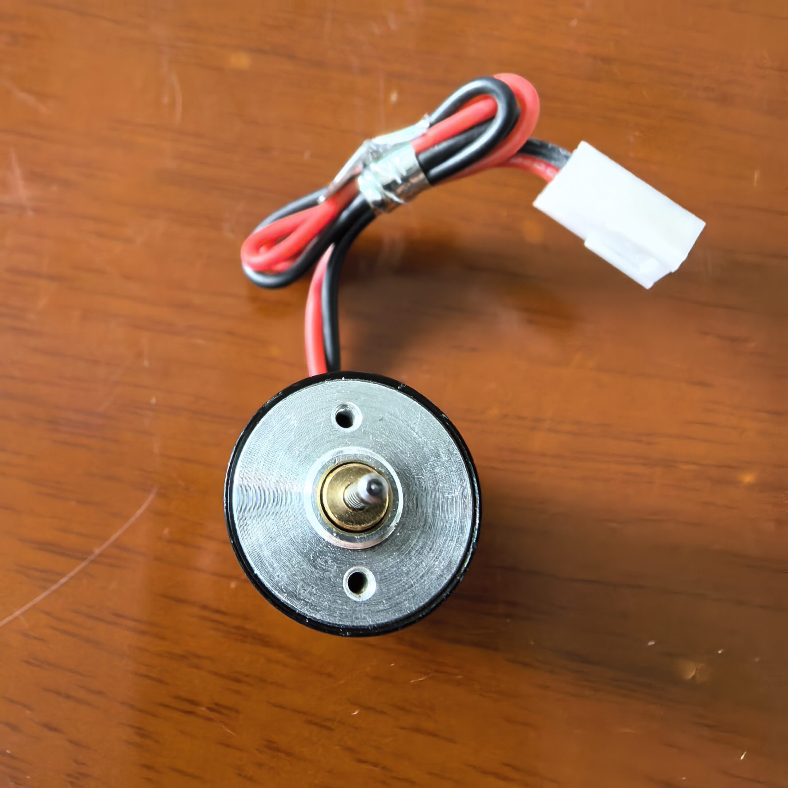
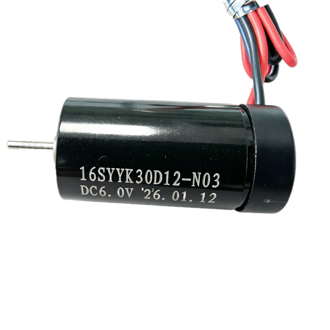
| Connection Type | Lead Wires / Terminals |
Potential Applications
Depending on its confirmed specifications and operating conditions, the 16SYYK30D06-N01 Brushed Coreless Motor may suit:
- Instrument Drives: Rotary movement within compatible measurement and adjustment assemblies.
- Optical Mechanisms: Driving suitably designed focusing or alignment components.
- Miniature Actuators: Providing rotary input to small mechanical transmissions.
- Portable Equipment: Operating powered mechanisms within the available electrical and thermal limits.
- Automation Devices: Performing repeated movement coordinated with external controller commands.
Speed and Position Control
The motor’s speed changes with electrical input and mechanical load. A suitable controller can manage acceleration, running speed, and deceleration according to the application.
For closely regulated speed, a feedback system can compensate for load changes. For positioning tasks, a sensor or encoder can provide information about actual movement.
Timed operation alone does not establish a precise stopping position. The final position also depends on inertia, friction, braking behavior, and transmission characteristics.
Electrical Integration
Match the power supply and controller to the motor’s electrical requirements. Account for startup current and possible stall conditions when selecting the drive electronics.
Suitable current limiting can help manage excessive load demand. Avoid prolonged stalled operation, which can cause rapid winding heating.
Assess temperature rise throughout the intended duty cycle. Frequent starts, reversals, and extended loading can create different thermal conditions from steady unloaded operation.
Installation and Mechanical Support
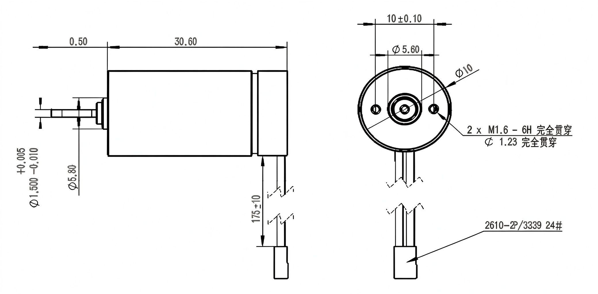
Check the mounting arrangement, shaft geometry, and installation clearance against the product drawing. Use a coupling that fits correctly without forcing or misaligning the connected components.
Avoid excessive axial or radial forces on the shaft. Provide independent support where the driven mechanism requires it.
Protect the motor leads from repeated bending, pulling, and contact with moving parts. Allow appropriate heat dissipation within the equipment enclosure.
Operating Life and Application Selection
Brush and commutator wear influence the motor’s service life. Load, speed, switching frequency, and environmental conditions all affect wear during operation.
Evaluate the required torque, response, operating cycle, and expected service life together. Testing the 16SYYK30D06-N01 within the intended assembly helps confirm controller compatibility, movement performance, noise, and temperature rise.

Reviews
There are no reviews yet.