
Description
General Specifications
| Parameter | Specification |
|---|---|
| Winding Type | Unipolar / Bipolar |
| Motor Configuration | Captive / Non-Captive / External Linear Actuator |
Electrical Specifications
| Parameter | Unit | Option 1 | Option 2 | Option 3 | Option 4 |
|---|---|---|---|---|---|
| Step Angle | ° | 7.5 | 7.5 | 15 | 15 |
| Operating Voltage | V | 5 | 12 | 5 | 12 |
| Current per Phase | mA | 370 | 160 | 370 | 160 |
| Resistance per Phase | Ω | 13.5 | 70 | 13.5 | 70 |
| Inductance per Phase | mH | 12.5 | 65 | 9.5 | 47 |
Linear Travel per Step
| Travel Option | Unit | 7.5° Step Angle | 15° Step Angle |
|---|---|---|---|
| Option A | mm/step | 0.0127 | 0.0254 |
| Option B | mm/step | 0.0254 | 0.0508 |
| Option C | mm/step | 0.0508 | 0.1016 |
Note: Parameters can be customized according to customer requirements. Available lead screw diameters: ① 3.5 mm, ② 4.77 mm. Available leads: ① 0.3048, 0.6096, 1.0, 1.2192, 2.0, 2.4384, 4.0, 8.0… (mm); ② 0.635, 1.27, 2.54, 5.08, 10.16… (mm). Step size = (step angle / 360) × lead (mm).
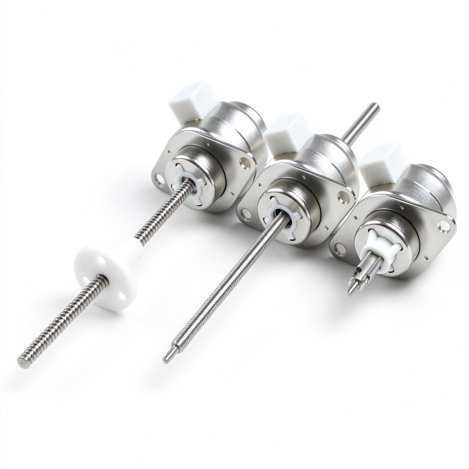
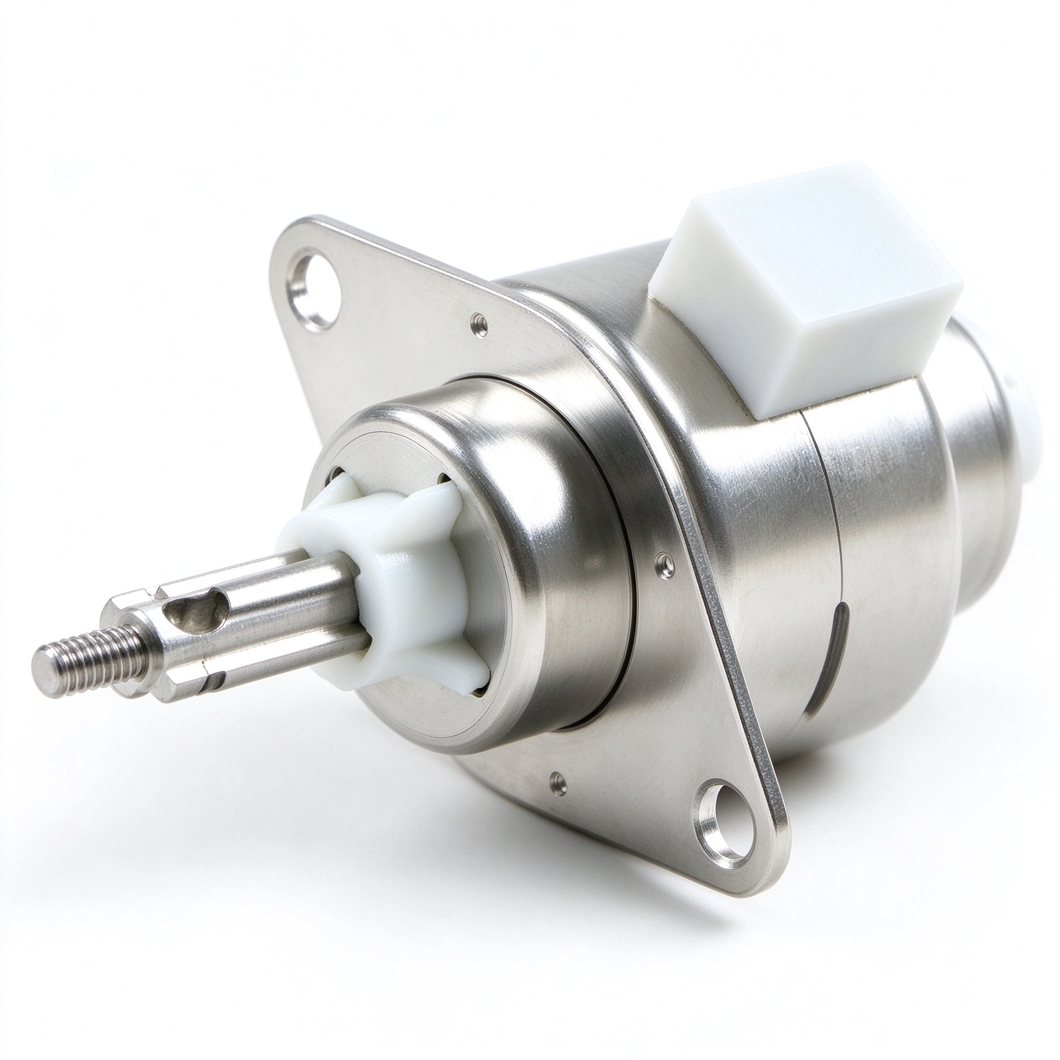
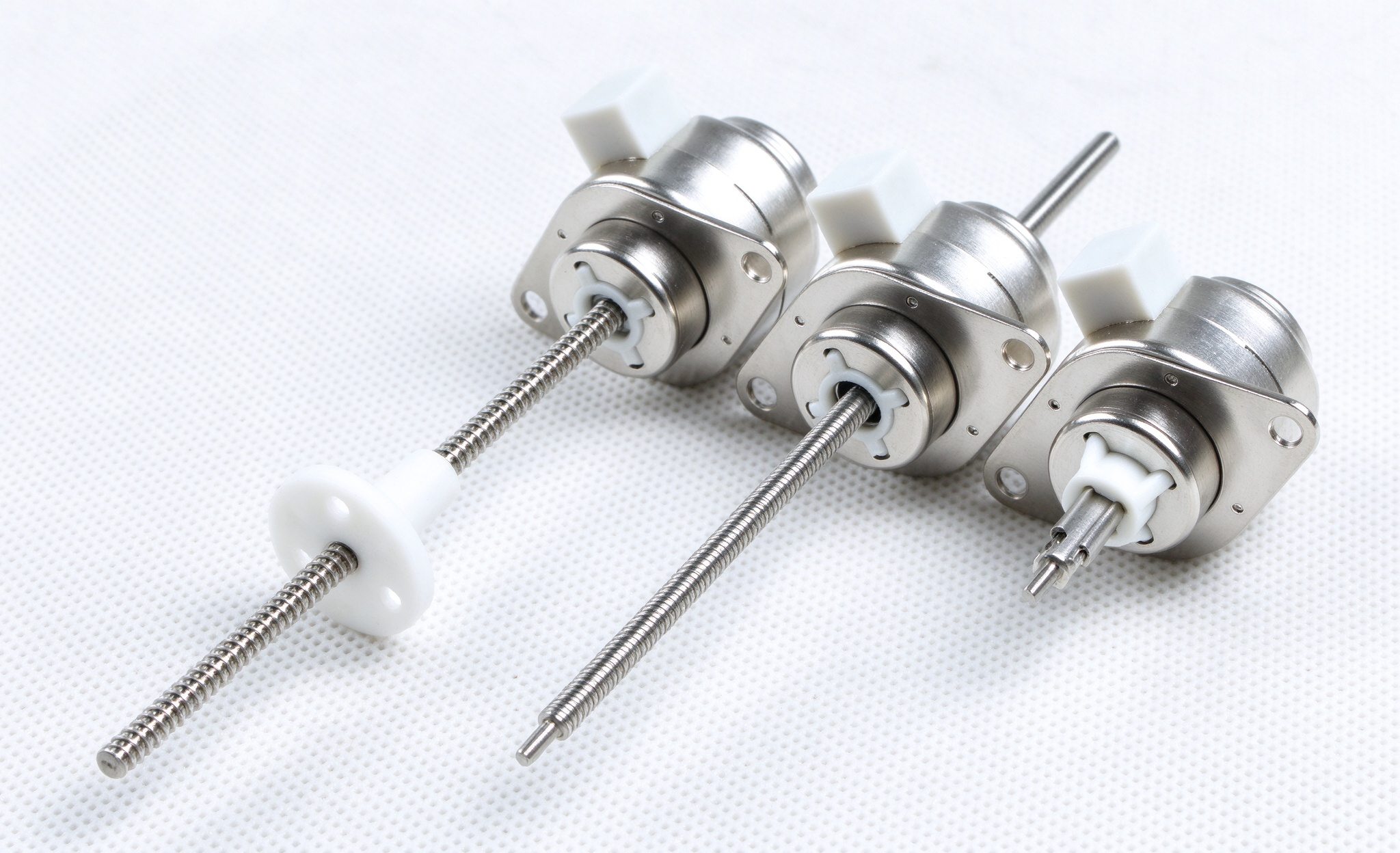
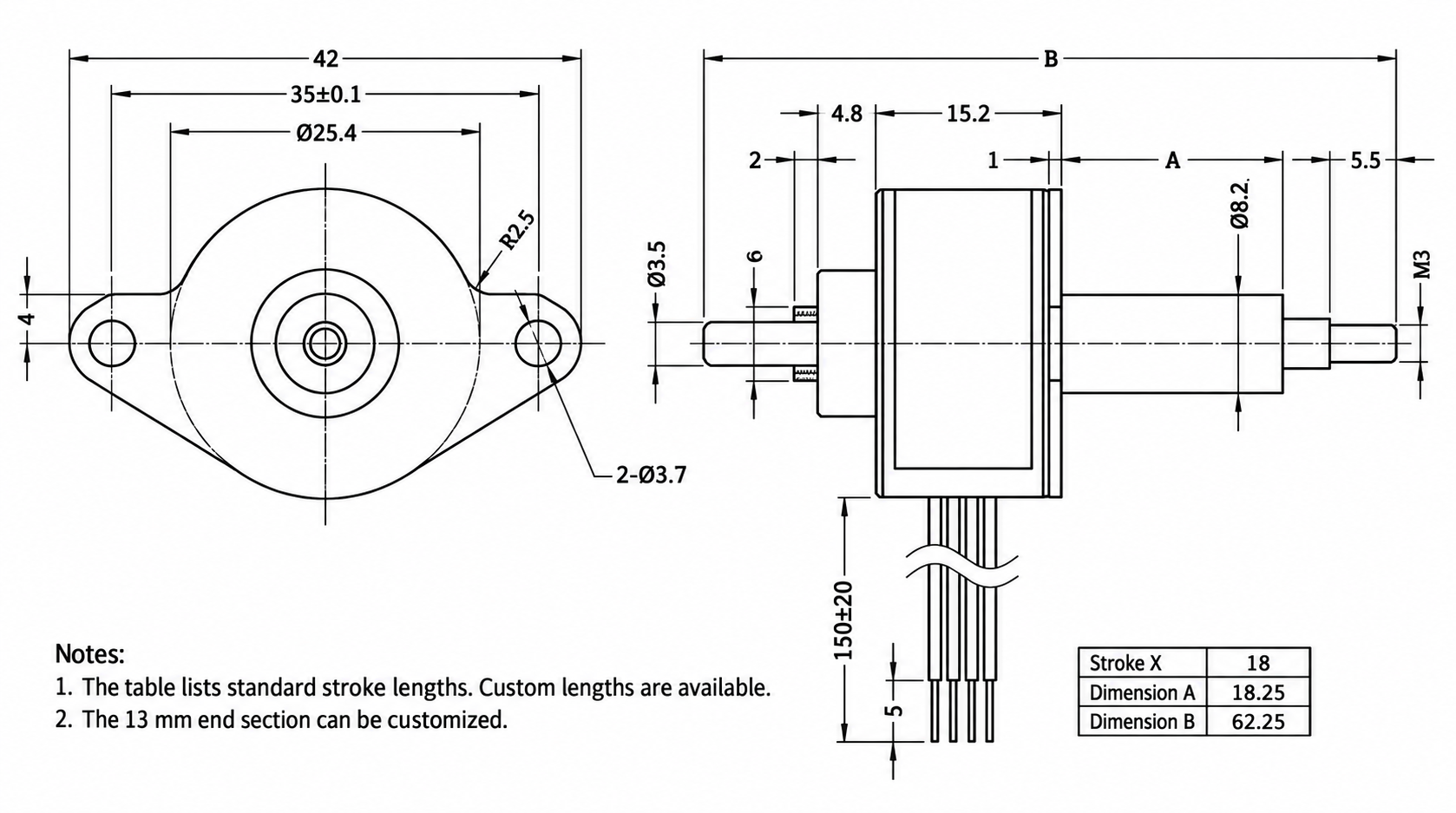
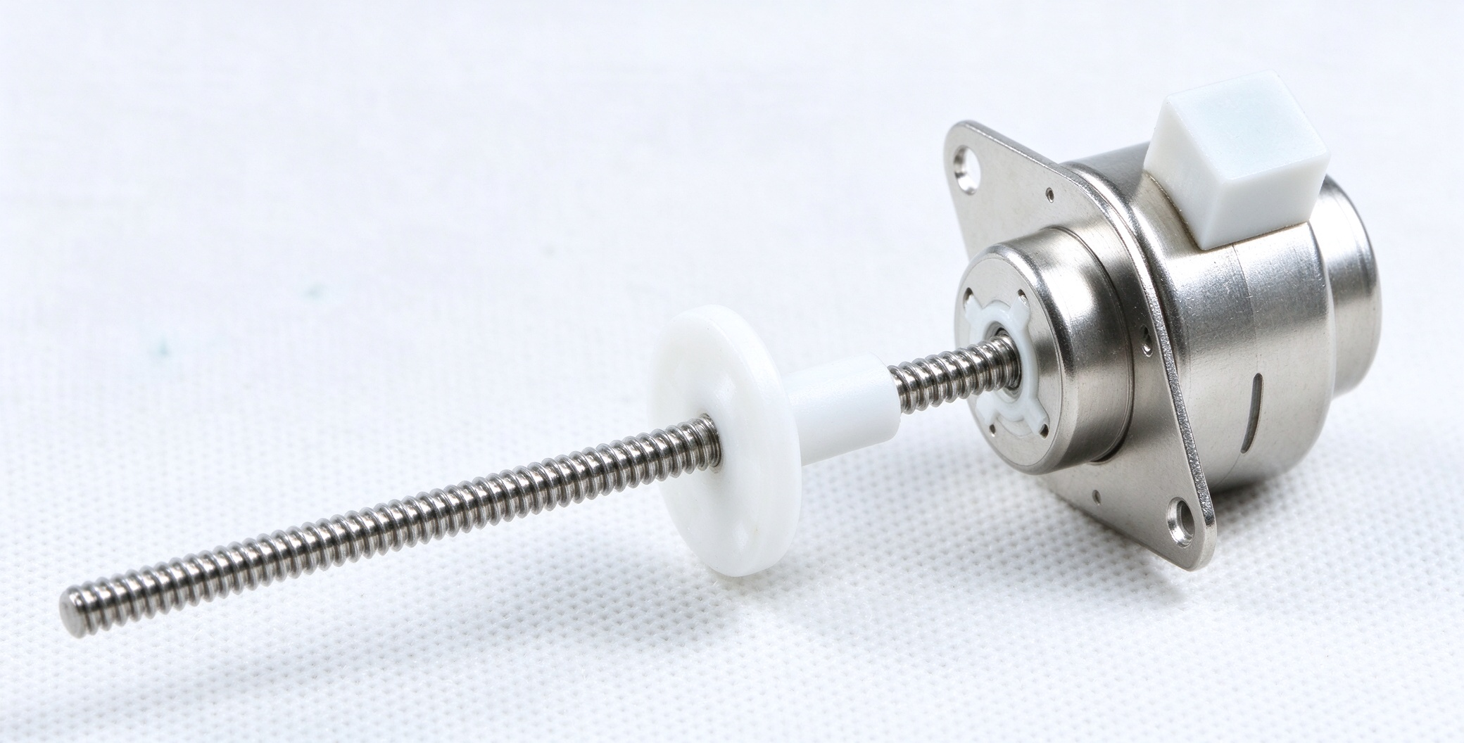
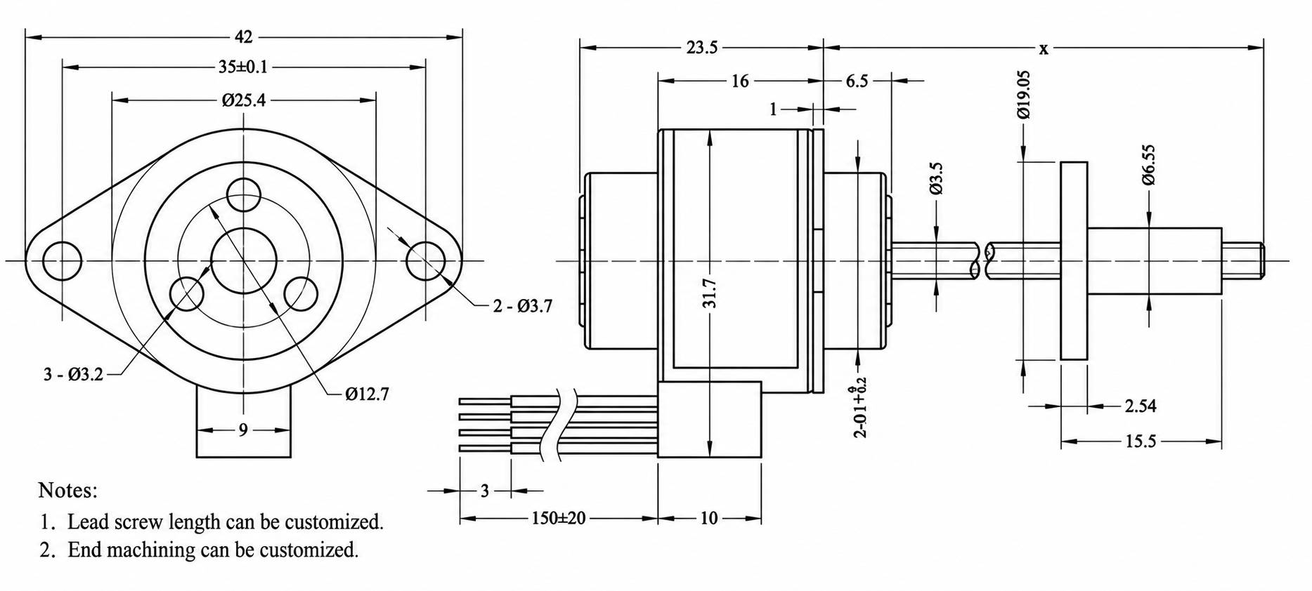
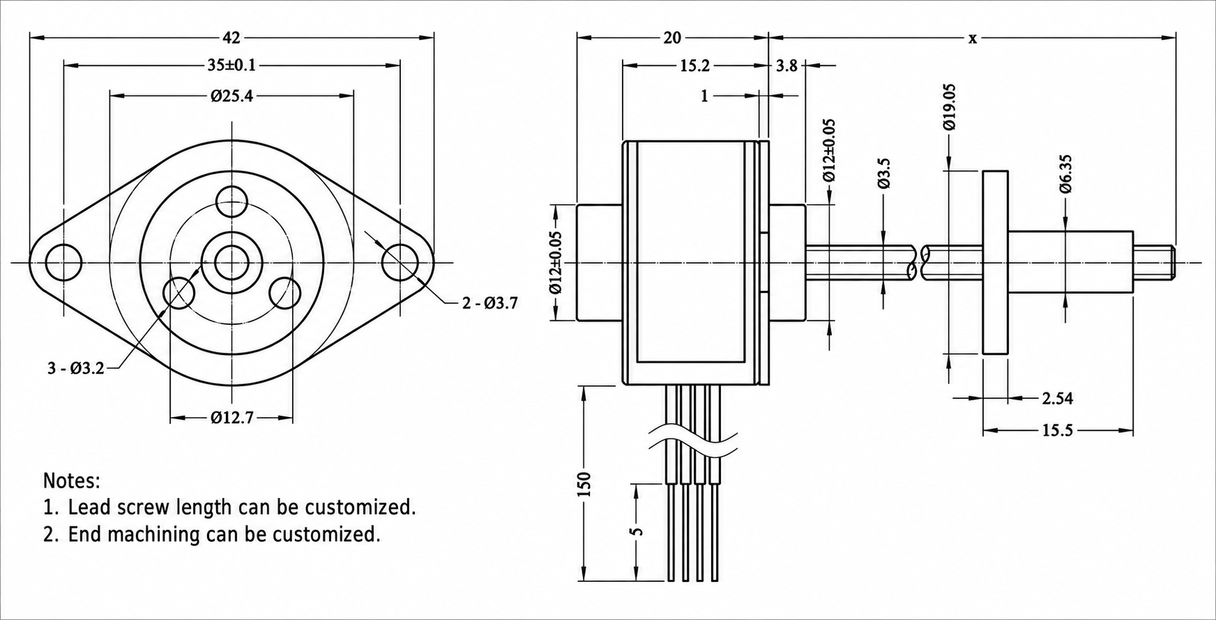
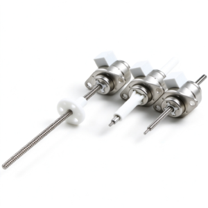
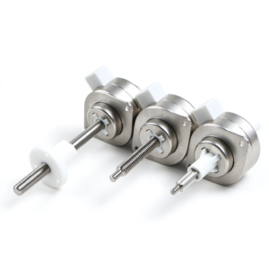
1. Fixed-shaft type; available in three external dimensions.
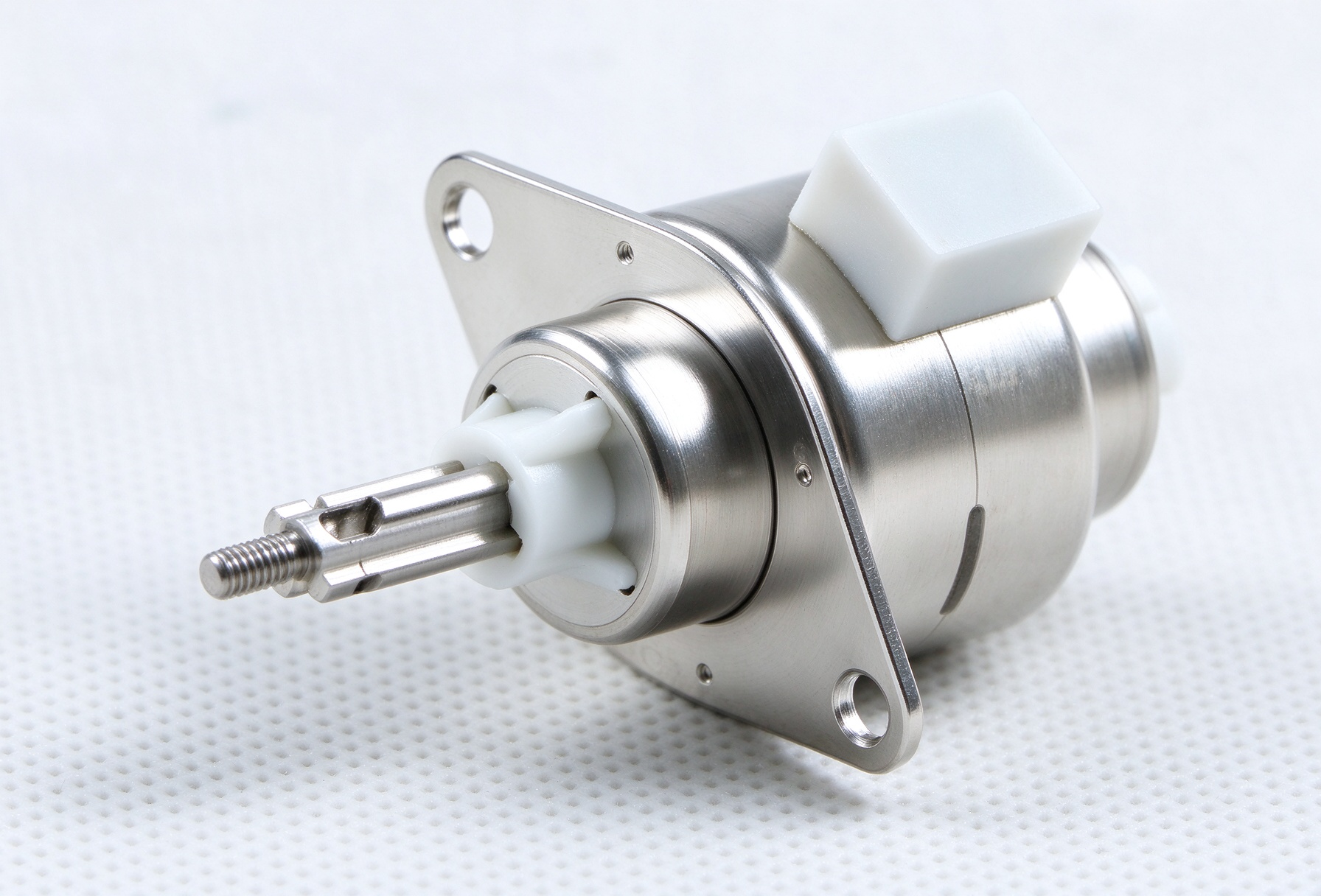
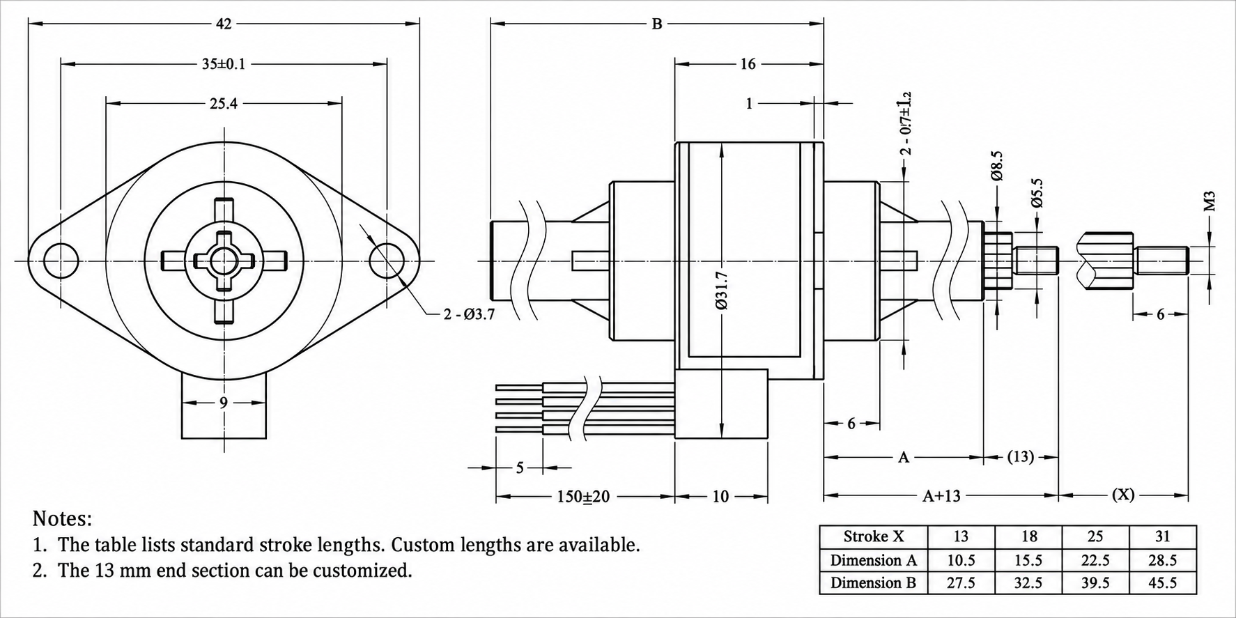
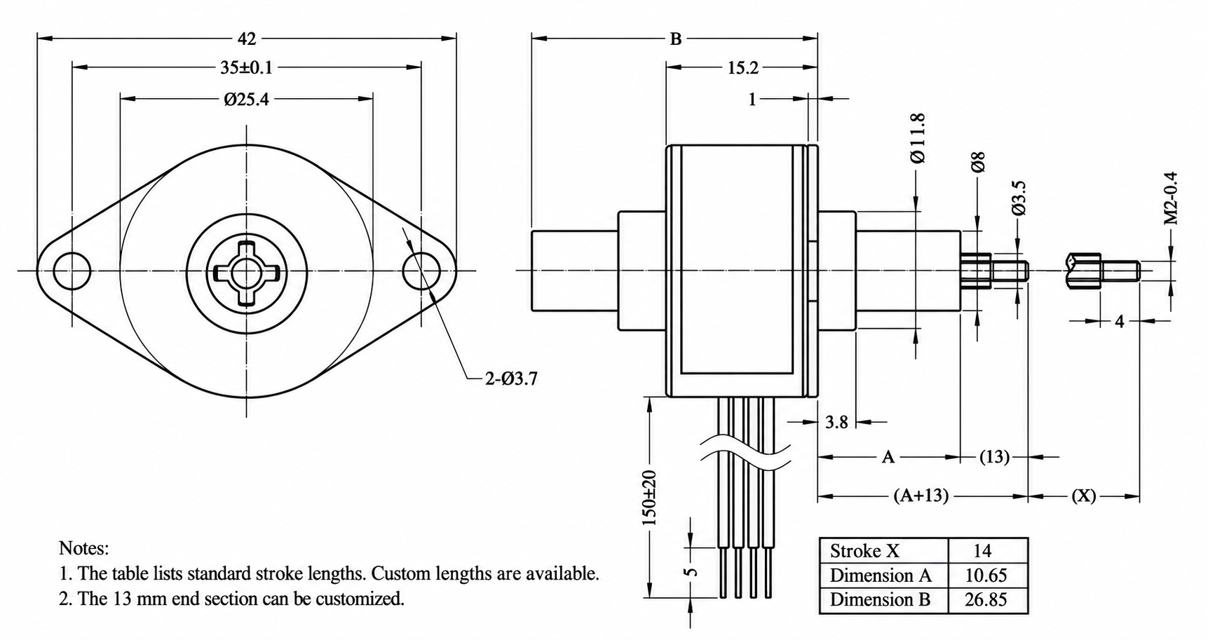
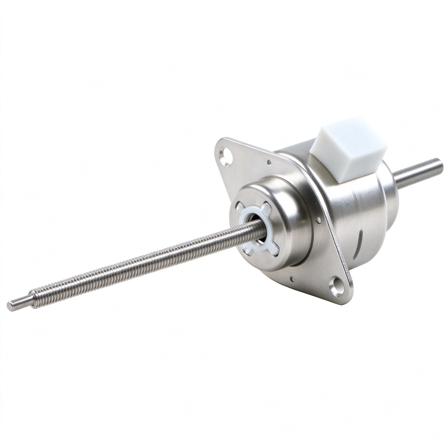
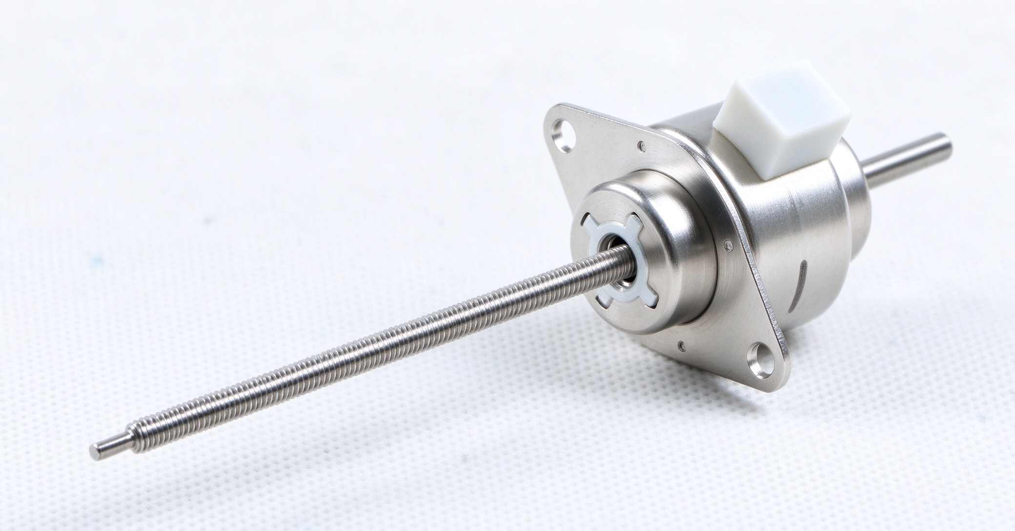
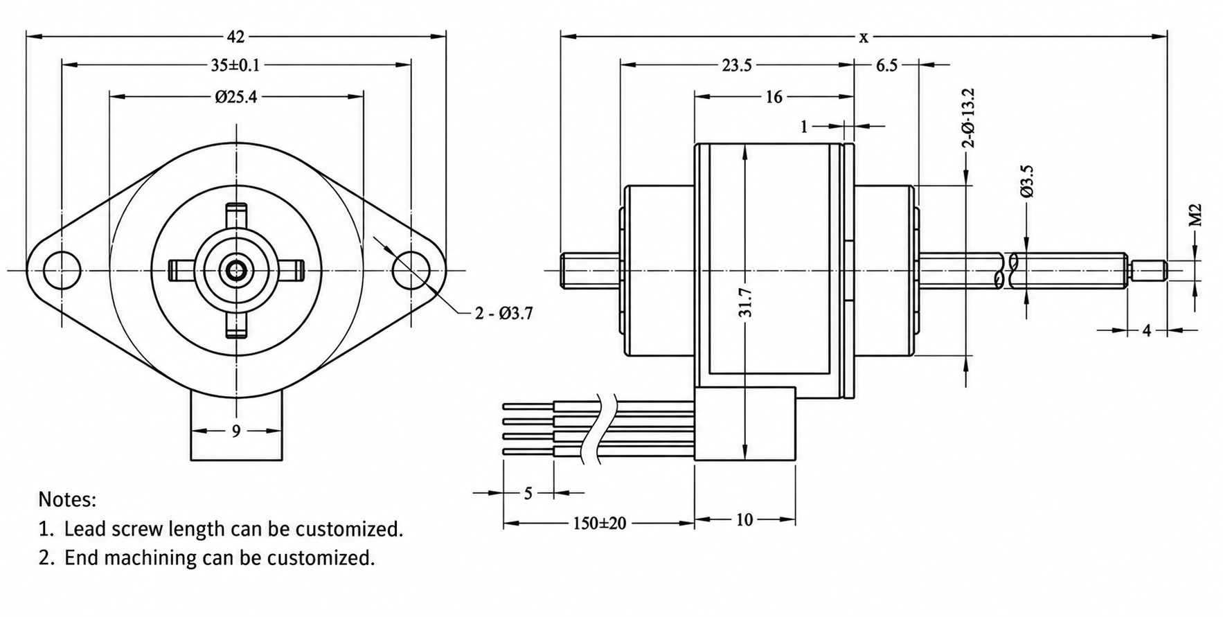
2. Through-shaft type; available in two external dimension options.
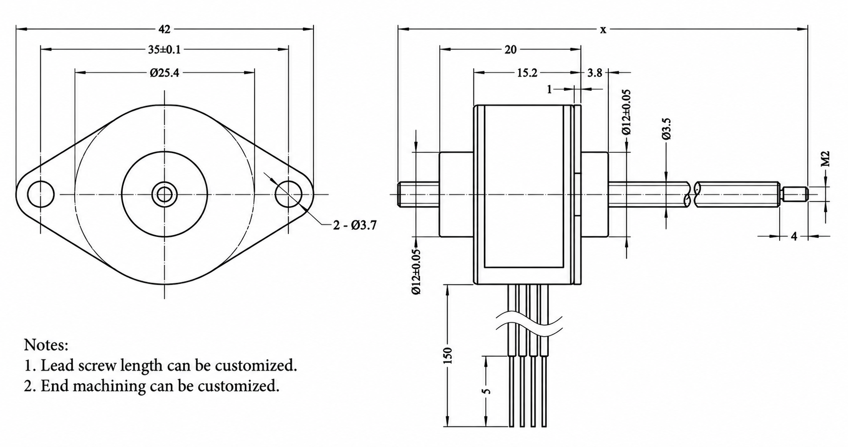
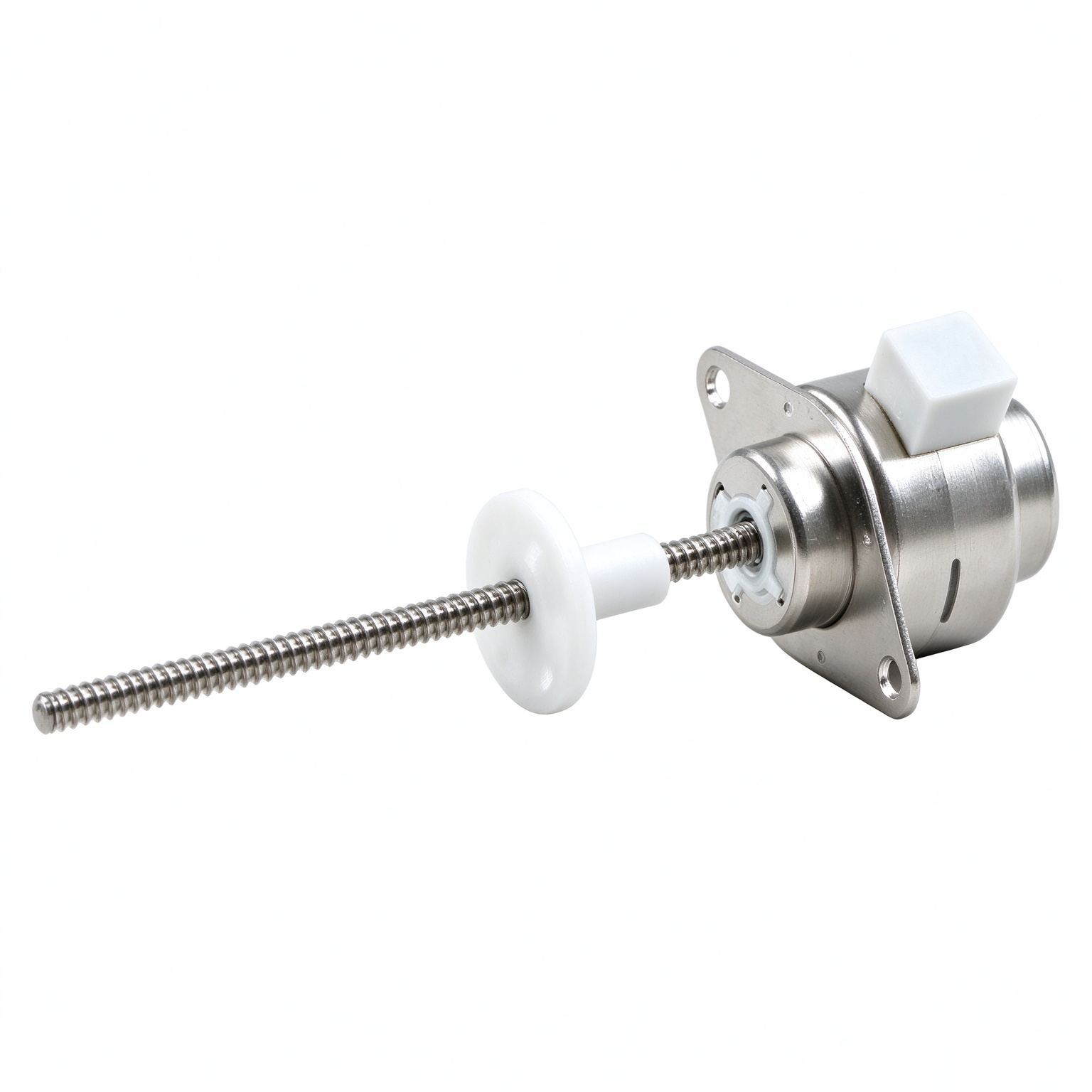
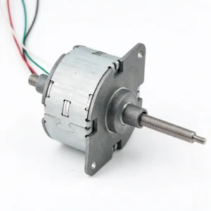
3. External-drive type: Available in two different physical dimensions.
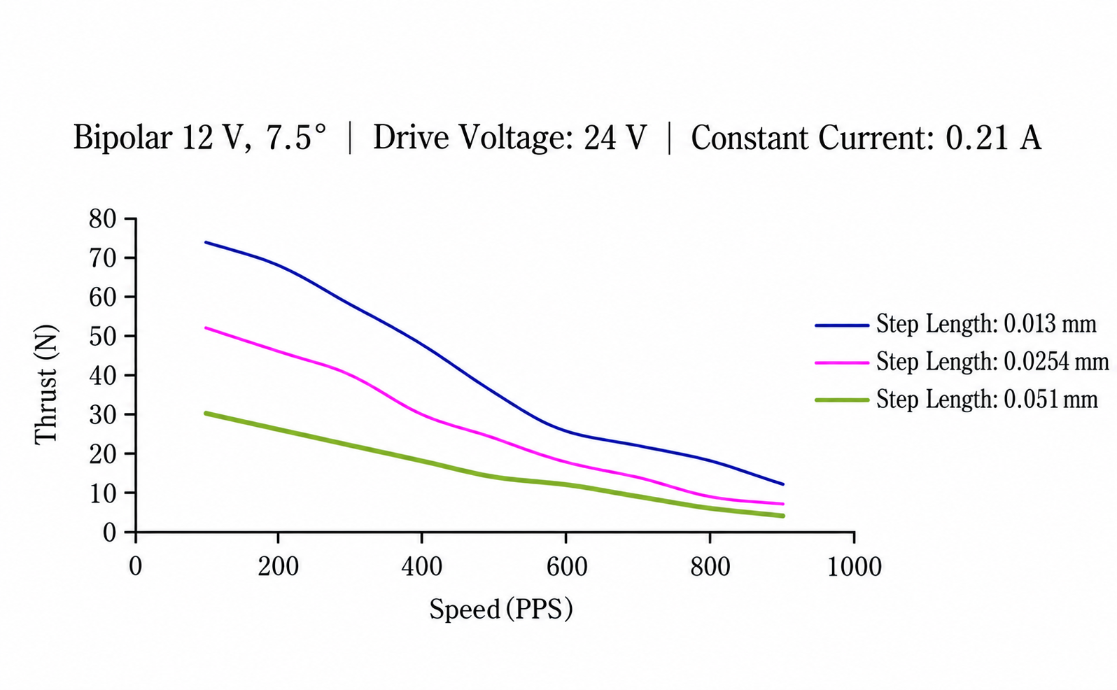
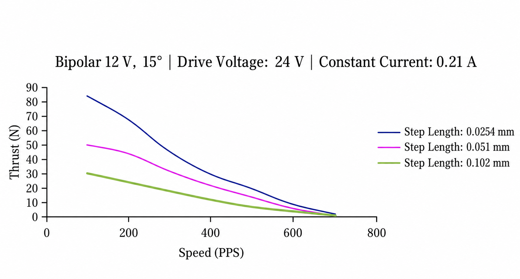
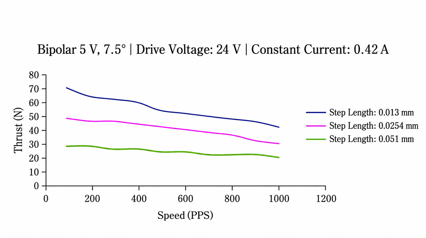
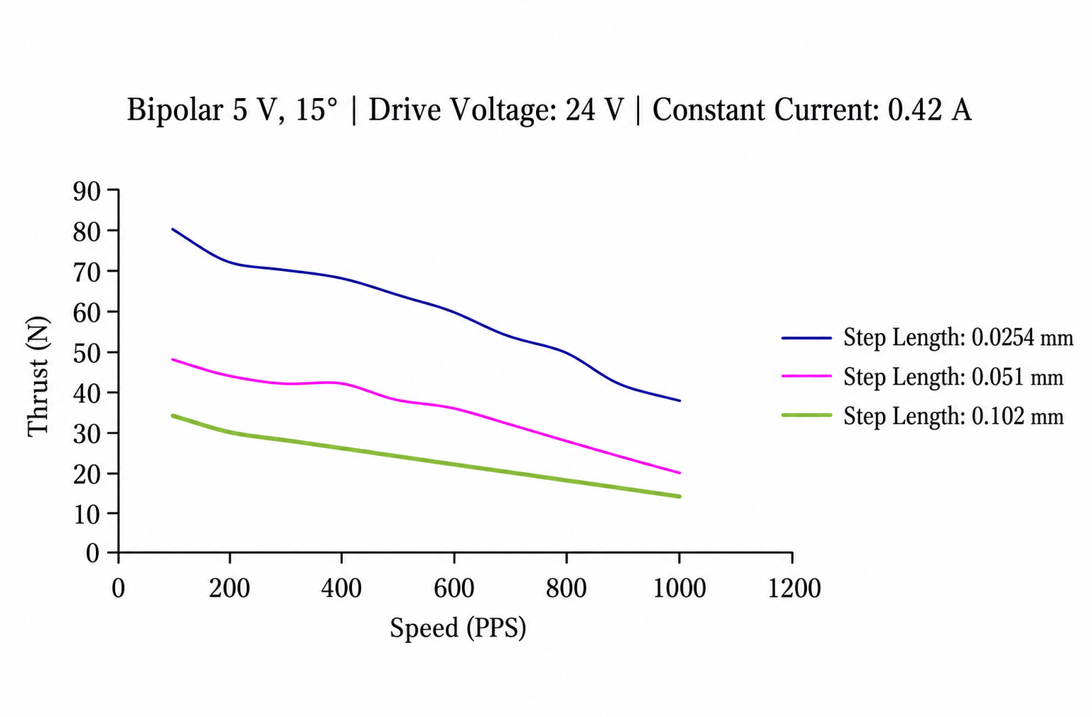
Step speed and thrust curve
Controlled Linear Movement
The motor operates through sequential winding excitation. Each commanded step produces movement through the screw mechanism, allowing a compatible controller and driver to manage travel direction and distance.
This operating principle supports applications that require incremental adjustment or programmed movement sequences. Actual travel per step depends on the selected motor and screw configuration.
Integrated Motor and Transmission
The combined motor and screw mechanism can simplify the arrangement of a linear actuation assembly. Depending on the selected configuration, the shaft or driven nut provides the movement required by the equipment.
This approach gives designers an alternative to connecting a separate rotary motor to an external transmission. Mounting arrangements, load connections, and guidance should match the actuator structure.
Forward and Reverse Operation
A compatible drive system can command movement in either direction for extension and retraction cycles. Designers can incorporate these movements into automatic adjustment routines, positioning sequences, and equipment setup procedures.
Suitable acceleration and deceleration settings help the motor move the intended load within its operating capability. Motion profiles should account for friction, load changes, and available travel.
Flexible Equipment Integration
The Φ25 Series can be considered for mechanisms that need electrically controlled axial movement. Potential applications include:
- Instrument adjustment assemblies
- Guided positioning slides
- Optical adjustment mechanisms
- Automated fixtures
- Appliance actuation systems
- Small automation mechanisms
The appropriate configuration depends on the required thrust, travel speed, stroke, mounting space, and operating cycle.
Positioning and Reference Control
The controller determines commanded displacement through the number of motor steps. A homing routine or reference switch can establish a starting position before the mechanism begins its operating sequence.
For applications that require position verification, designers can incorporate suitable feedback. Overall positioning performance also depends on screw backlash, mechanical alignment, load conditions, and driver settings.
Mechanical Installation
Correct alignment helps the screw mechanism transfer movement to the load. External guides should support the moving assembly when necessary and reduce side forces or bending loads on the actuator.
Depending on the motor configuration, an external anti-rotation arrangement may be required. Appropriate travel limits help prevent the mechanism from reaching damaging end positions.
Driver and System Compatibility
Select a driver that matches the motor’s winding arrangement and electrical requirements. Drive current, excitation method, movement speed, and duty cycle influence motor operation and heating.
Evaluating the complete assembly under its intended working conditions helps confirm suitable motion settings, load support, and thermal performance. The Φ25 Series offers a practical basis for integrating step-controlled linear travel into equipment designs.

Reviews
There are no reviews yet.