
Description
General Specifications
| Parameter | Specification |
|---|---|
| Winding Type | Unipolar / Bipolar |
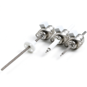
| Motor Configuration | Captive / Non-Captive / External Linear Actuator |
Electrical Specifications
| Parameter | Unit | Option 1 | Option 2 | Option 3 | Option 4 |
|---|---|---|---|---|---|
| Step Angle | ° | 7.5 | 7.5 | 15 | 15 |
| Operating Voltage | V | 5 | 12 | 5 | 12 |
| Current per Phase | mA | 560 | 230 | 560 | 230 |
| Resistance per Phase | Ω | 9 | 52 | 9 | 52 |
| Inductance per Phase | mH | 11.5 | 72 | 8 | 56 |
Linear Travel per Step
| Travel Option | Unit | 7.5° Step Angle | 15° Step Angle |
|---|---|---|---|
| Option A | mm/step | 0.0127 | 0.0254 |
| Option B | mm/step | 0.0254 | 0.0508 |
| Option C | mm/step | 0.0508 | 0.1016 |
Note: Parameters can be customized according to customer requirements. Available lead screw diameters: ① 6.35 mm, ② 4.77 mm. Available leads: ① 0.6096, 1.0, 1.2192, 1.27, 2.4384, 2.54, 4.0, 8.0… (mm); ② 0.635, 1.27, 2.54, 5.08, 10.16… (mm). Step size = (step angle / 360) × lead (mm).
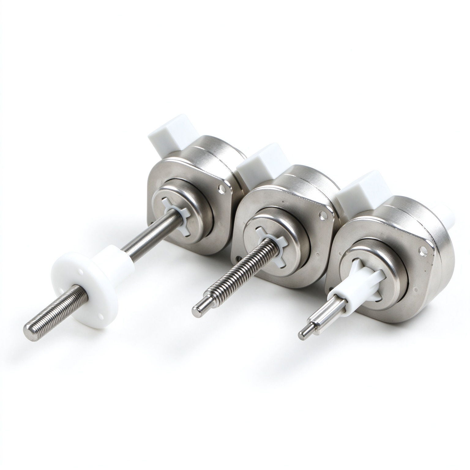
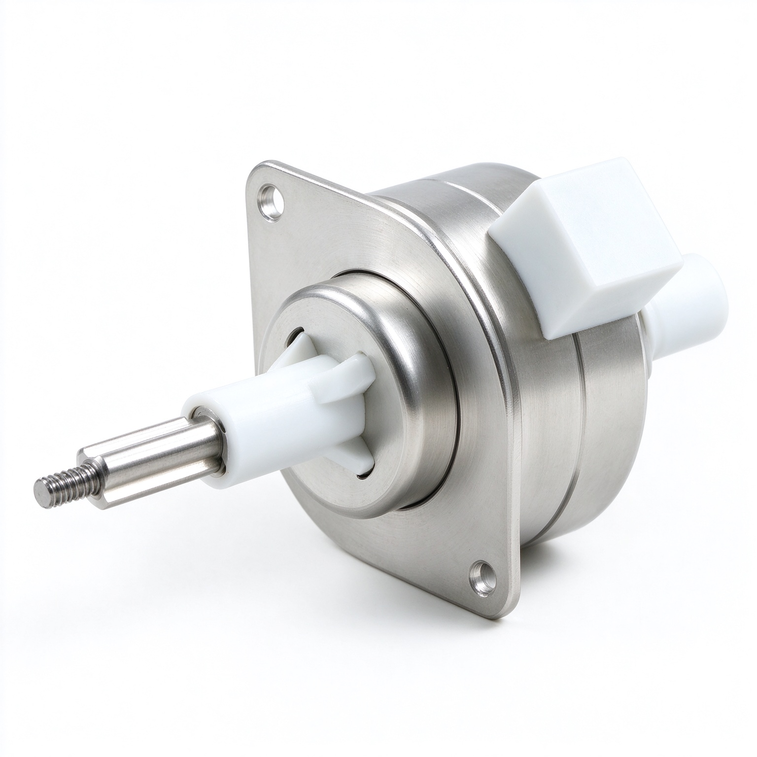
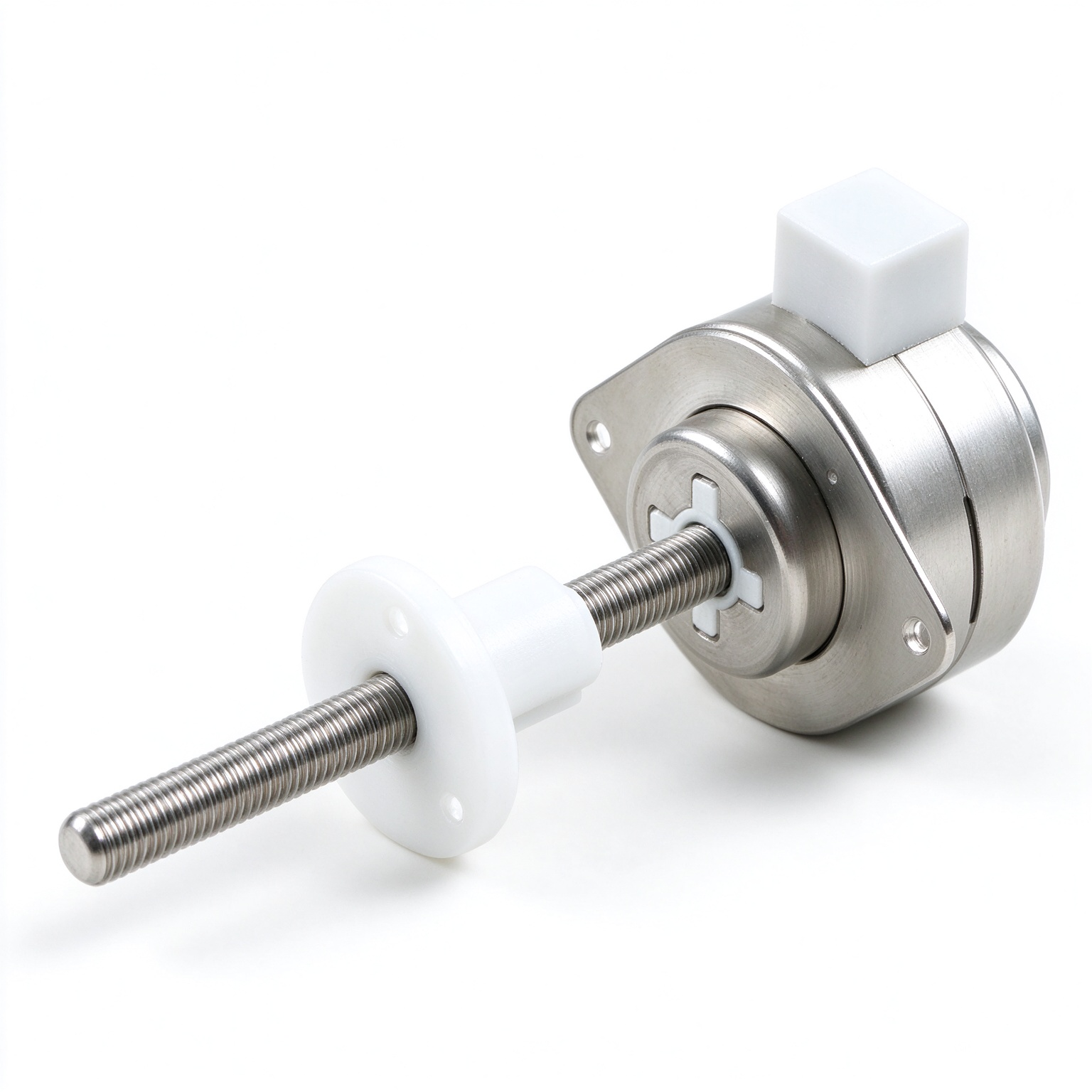
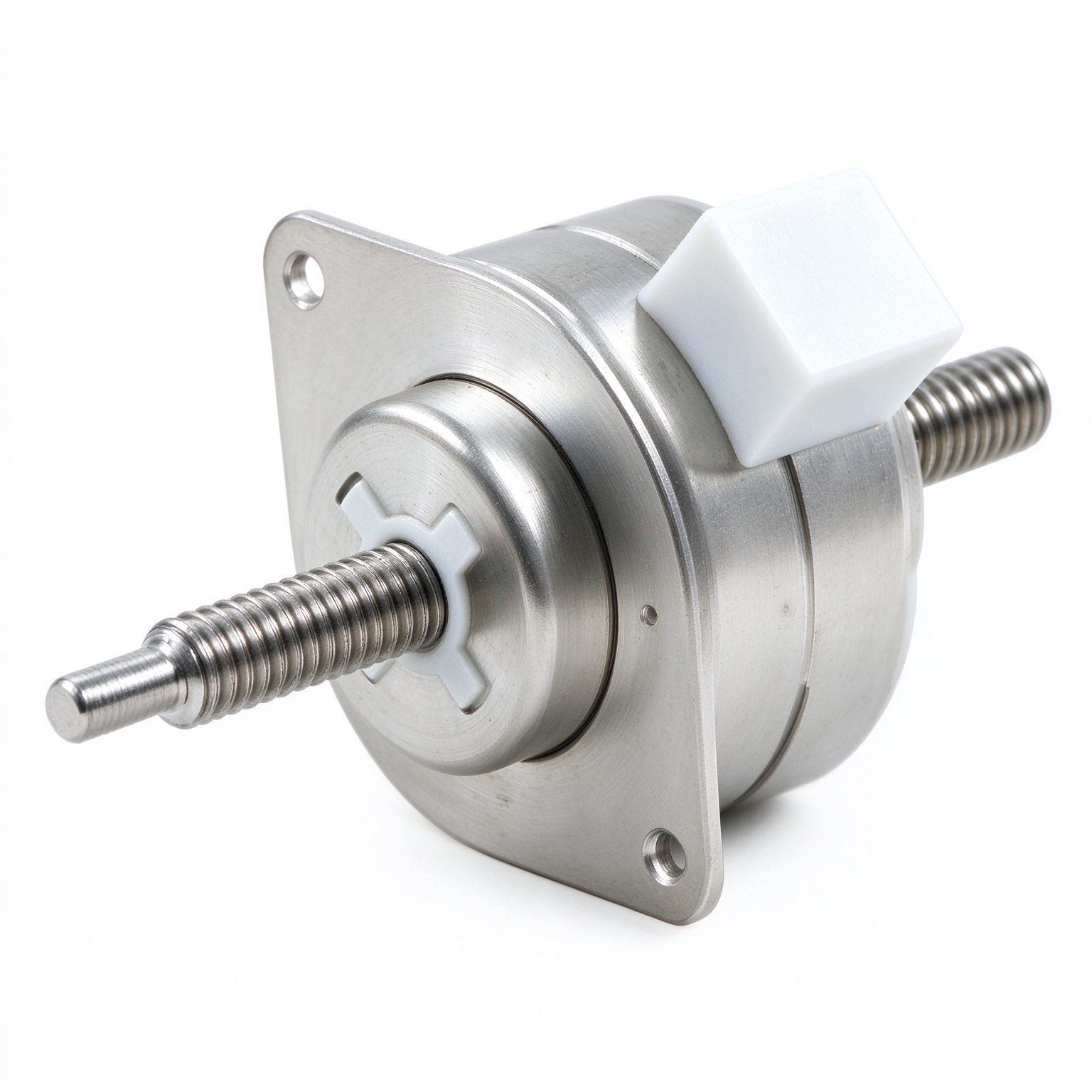
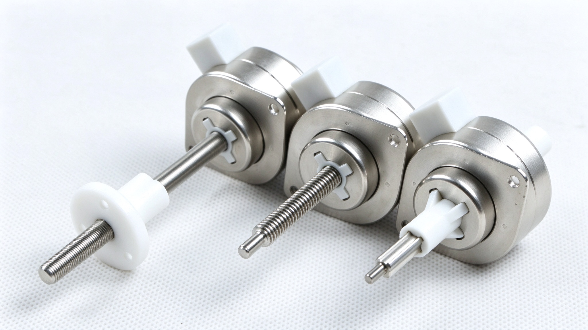
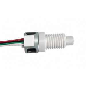
1. Fixed-shaft type; available in two external dimension options.
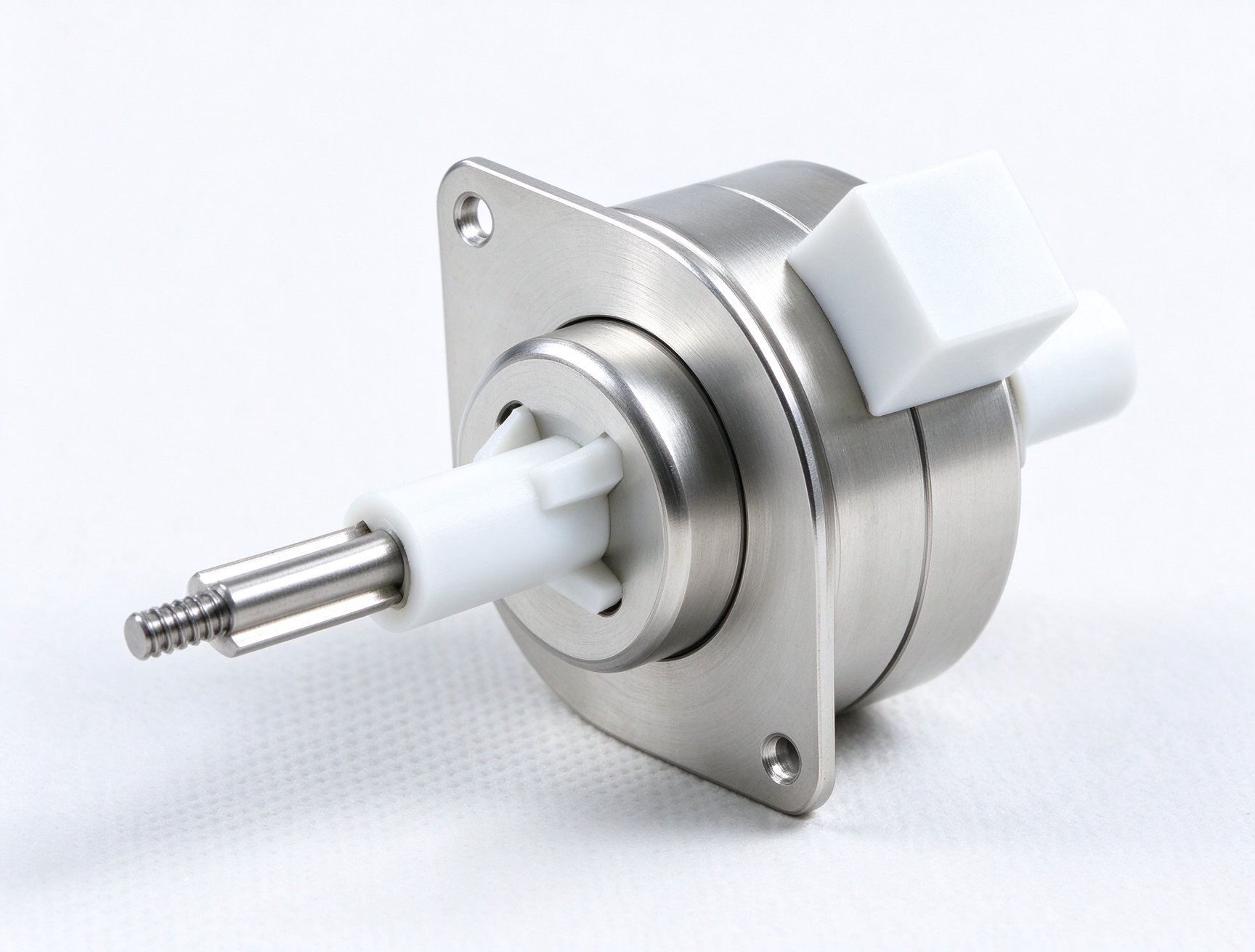
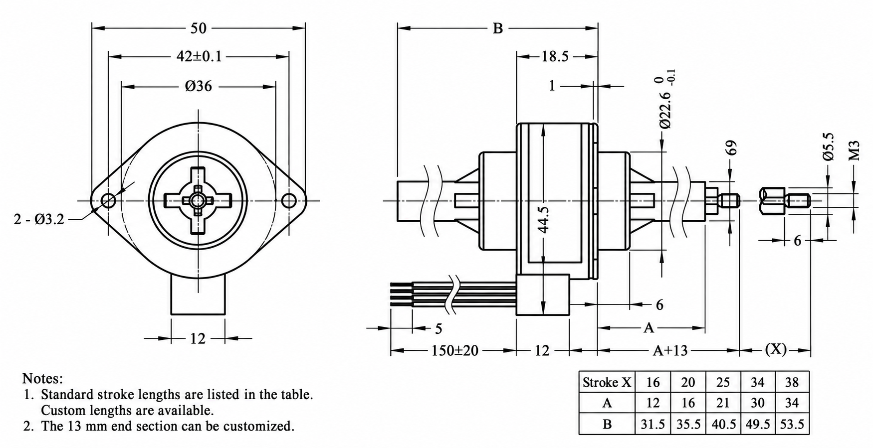
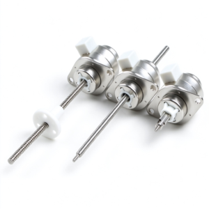
2. Through-shaft type
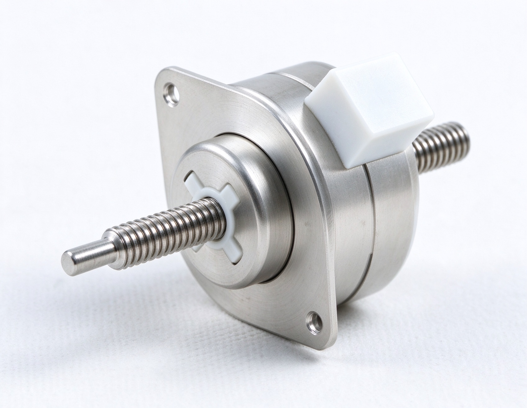
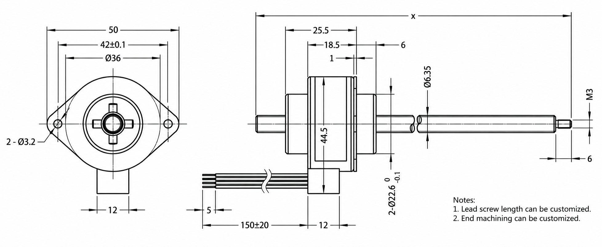
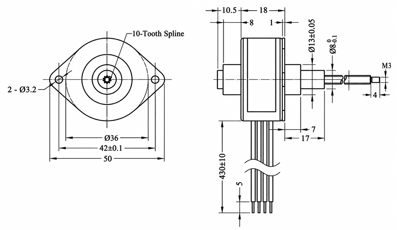
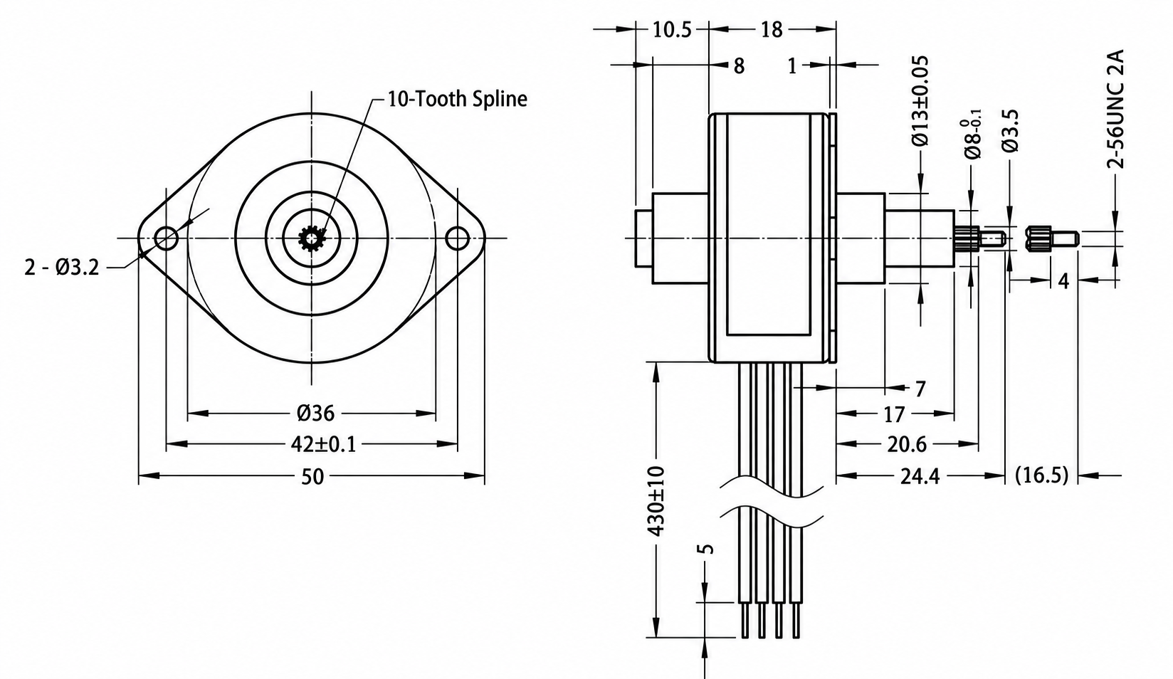
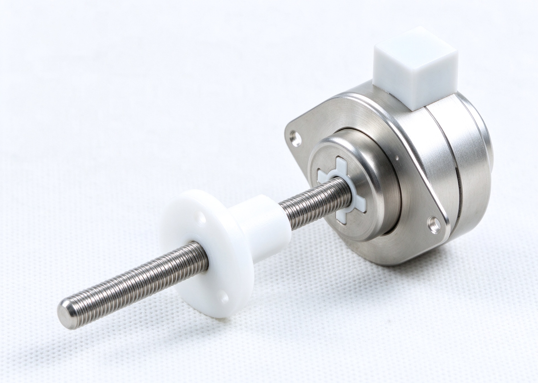
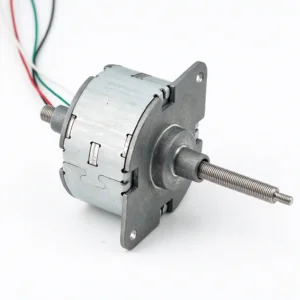
3. Externally-driven type
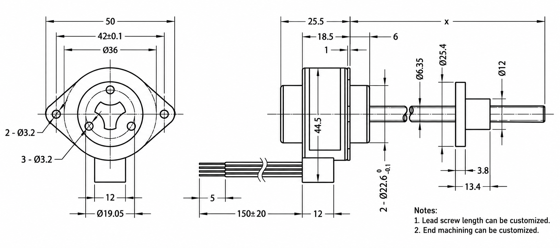
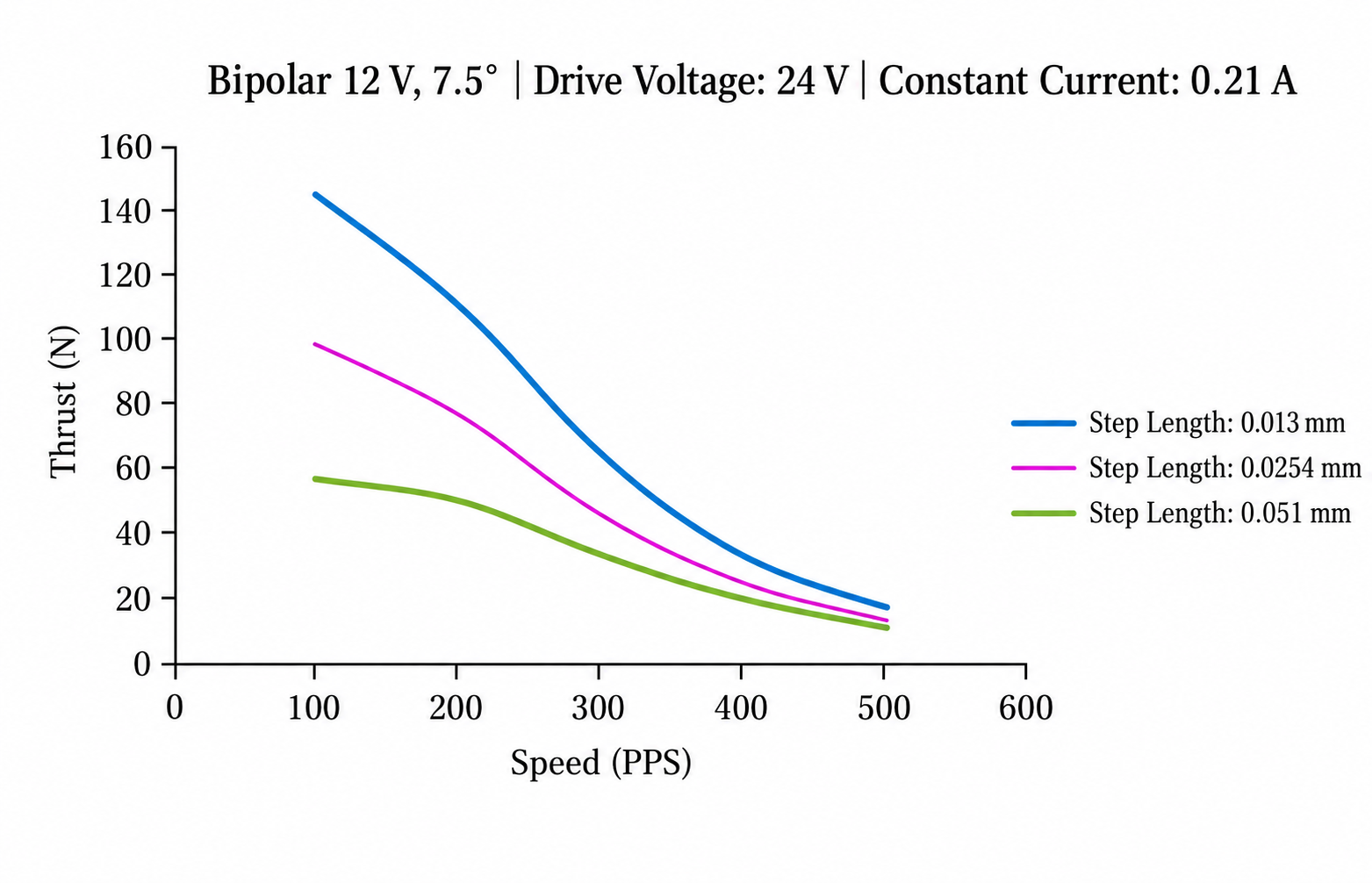
Step speed and thrust curve
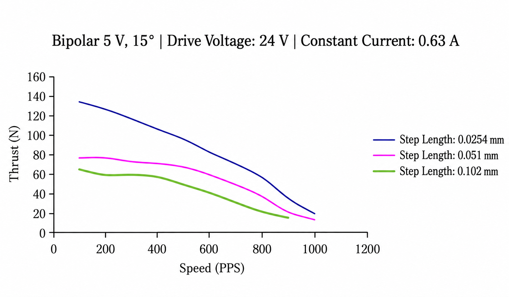
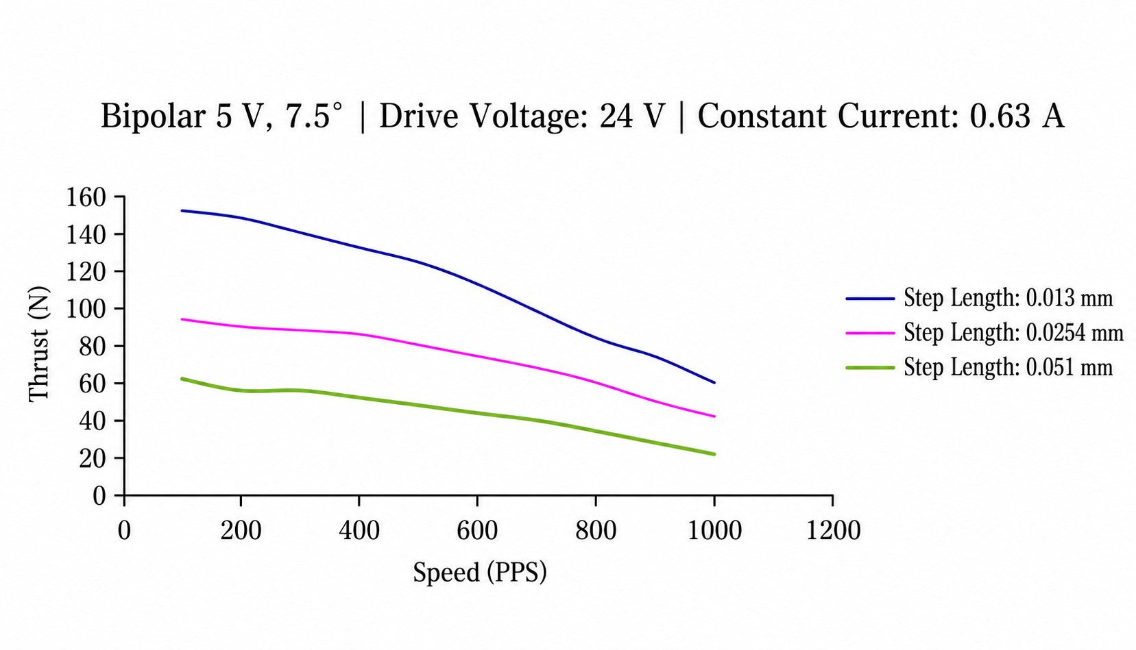
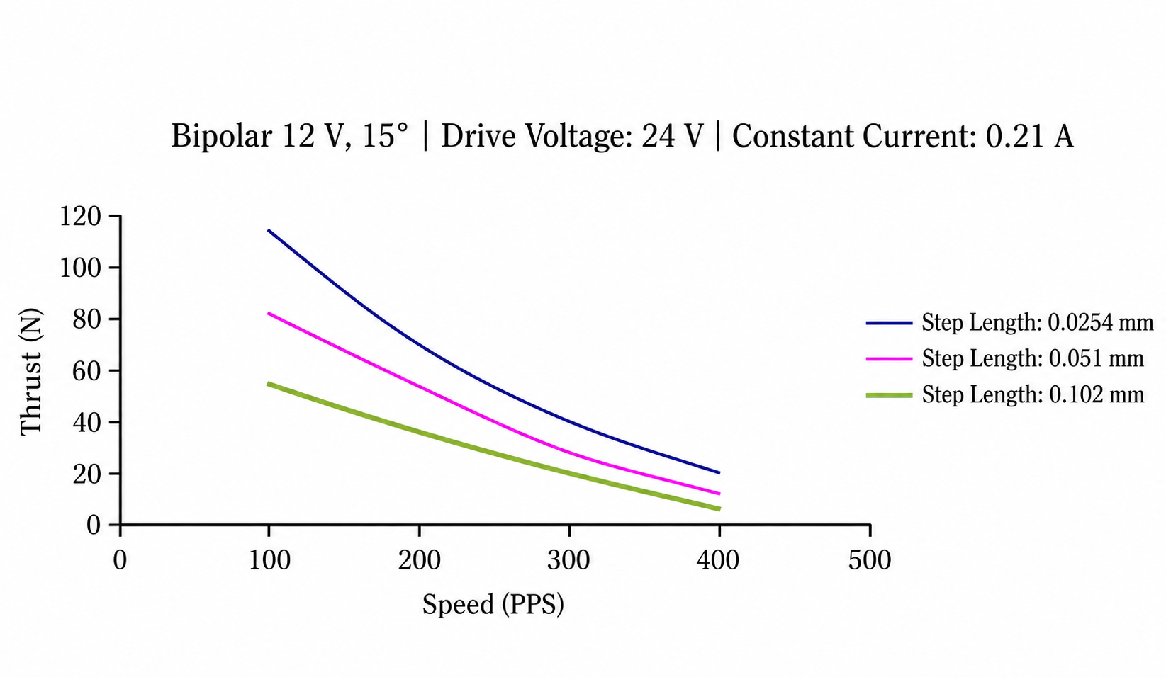
Step-Controlled Linear Travel
Sequential electrical excitation drives the motor through individual steps. The screw mechanism translates this stepping action into axial movement, allowing a compatible controller to manage commanded travel through the number and frequency of steps.
This operating principle supports programmed adjustment sequences and movement between defined positions. Actual displacement depends on the selected step angle, screw lead, and drive mode.
Integrated Screw-Driven Mechanism
Combining the motor with a screw transmission can simplify the mechanical arrangement of an actuator assembly. It also reduces the need to connect a separate rotary motor to an additional linear transmission.
The selected configuration determines how the shaft or nut moves and connects to the load. Mounting, guidance, and anti-rotation requirements should match the structure of the chosen motor.
Bidirectional Movement
A compatible driver and controller can operate the motor in both directions. This enables forward and reverse travel for adjustment, opening and closing mechanisms, and automatic return sequences.
Designers can coordinate travel distance, movement speed, and pauses within the equipment’s operating cycle. Appropriate acceleration and deceleration settings help the motor handle the load without exceeding its available thrust.
Adaptable Positioning Control
The Φ36 Series provides a basis for mechanisms that use incremental movement to adjust a component’s position. A reference switch or homing routine can establish the starting point before operation.
Where the application requires confirmation of actual movement, position feedback can supplement step commands. Positioning results depend on the complete assembly, including screw backlash, load variation, alignment, and control settings.
Potential Applications
The series can be considered for equipment such as:
- Automated adjustment fixtures
- Instrument positioning assemblies
- Guided linear slides
- Optical adjustment mechanisms
- Electrically operated opening and closing mechanisms
- Small automation and handling assemblies
Motor selection should match the required thrust, travel speed, stroke, duty cycle, and installation space.
Mechanical Integration
A correctly aligned installation helps the screw mechanism transfer motion to the driven component. Suitable guides should support loads that could otherwise apply lateral or bending forces to the actuator.
Depending on the configuration, the mechanism may require an external anti-rotation arrangement. Travel limits and sufficient clearance help protect the assembly throughout its operating range.
Electrical and Driver Compatibility
The motor requires a stepper driver that matches its winding arrangement and electrical specifications. Drive current, excitation mode, and step frequency influence movement behavior and motor temperature.
Evaluating the motor together with its driver, controller, and mechanical load helps establish suitable operating settings. Thermal conditions and repeated operating cycles should form part of this assessment.
Selection for Equipment Design
The Φ36 Series Permanent Magnet Linear Stepper Motors offer an integrated approach to step-controlled linear actuation. Matching the motor configuration and screw mechanism to the application allows designers to develop controlled movement for adjustment and positioning tasks.

Reviews
There are no reviews yet.