
Description
General Specifications
| Parameter | Specification |
|---|---|
| Winding Type | Unipolar / Bipolar |
| Motor Configuration | Captive / Non-Captive / External Linear Actuator |
Electrical Specifications
| Parameter | Unit | Option 1 | Option 2 | Option 3 | Option 4 |
|---|---|---|---|---|---|
| Step Angle | ° | 7.5 | 7.5 | 15 | 15 |
| Operating Voltage | V | 5 | 12 | 5 | 12 |
| Current per Phase | mA | 370 | 160 | 370 | 160 |
| Resistance per Phase | Ω | 13.5 | 74.5 | 13.5 | 76 |
| Inductance per Phase | mH | 6.5 | 38.5 | 4 | 25 |
Linear Travel per Step
| Travel Option | Unit | 7.5° Step Angle | 15° Step Angle |
|---|---|---|---|
| Option A | mm/step | 0.0127 | 0.0254 |
| Option B | mm/step | 0.0254 | 0.0508 |
| Option C | mm/step | 0.0508 | 0.1016 |
Note: Parameters can be customized according to customer requirements. Available lead screw diameters: 3.5 mm. Available leads: 0.3048, 0.6096, 1.0, 1.2192, 2.0, 2.4384, 4.0, 8.0… (mm). Step size = (step angle / 360) * lead (mm).
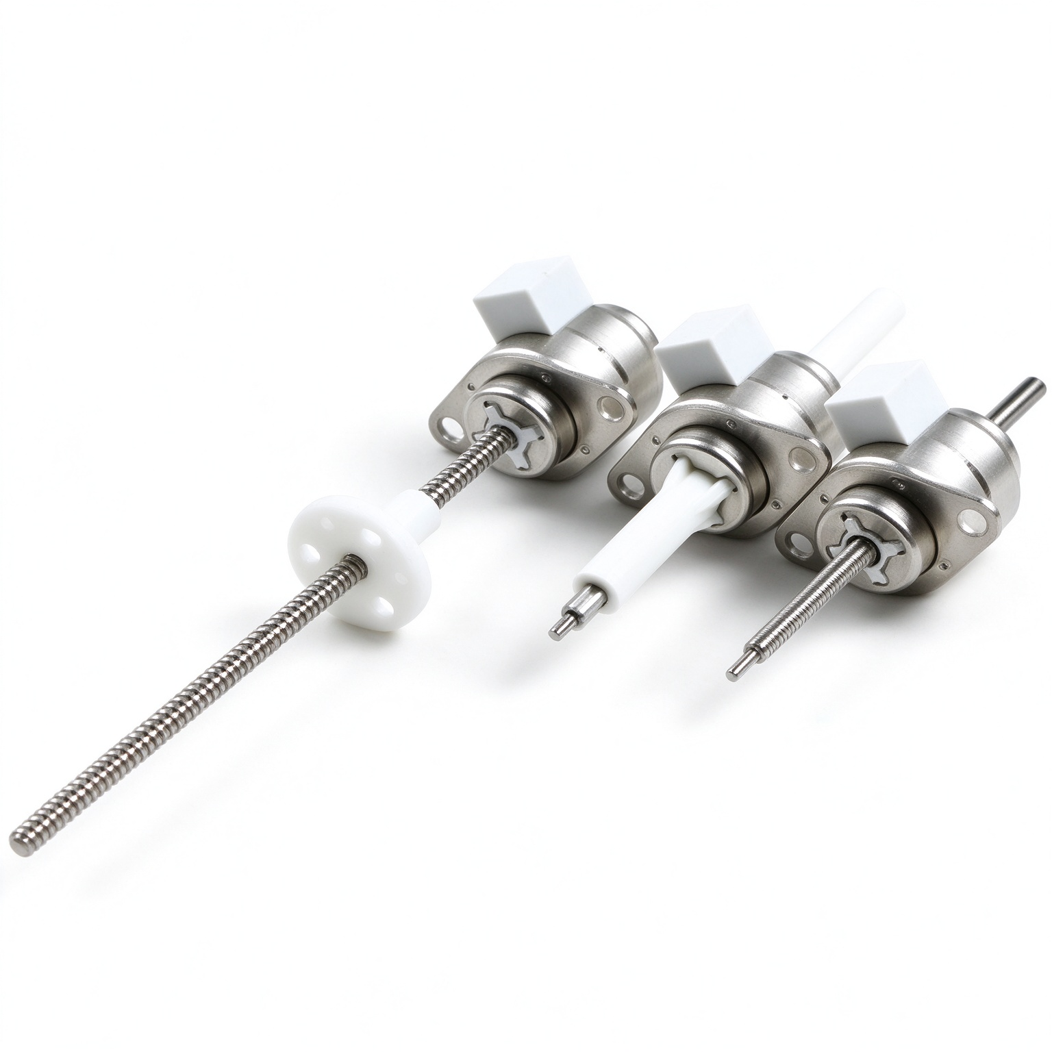
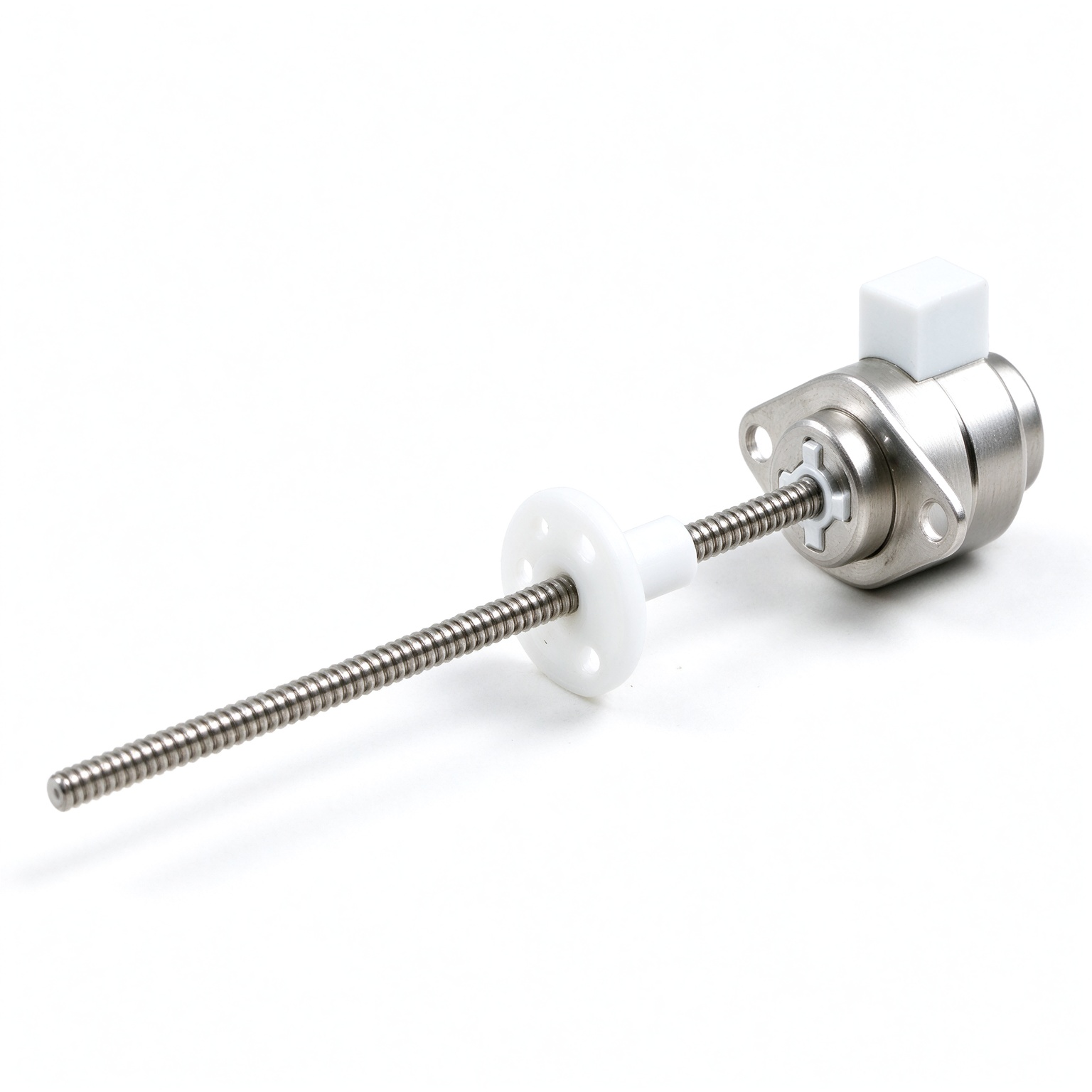
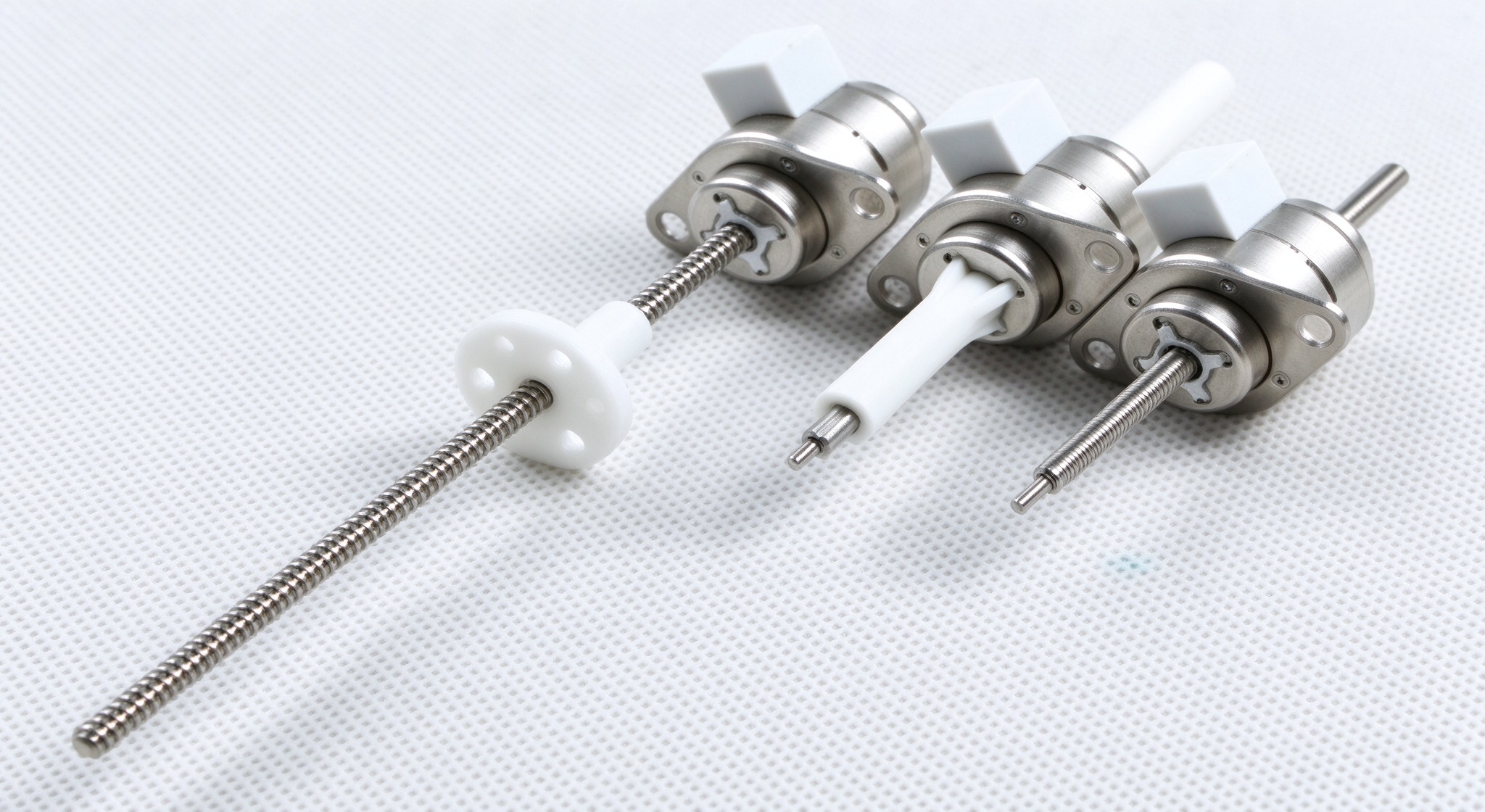
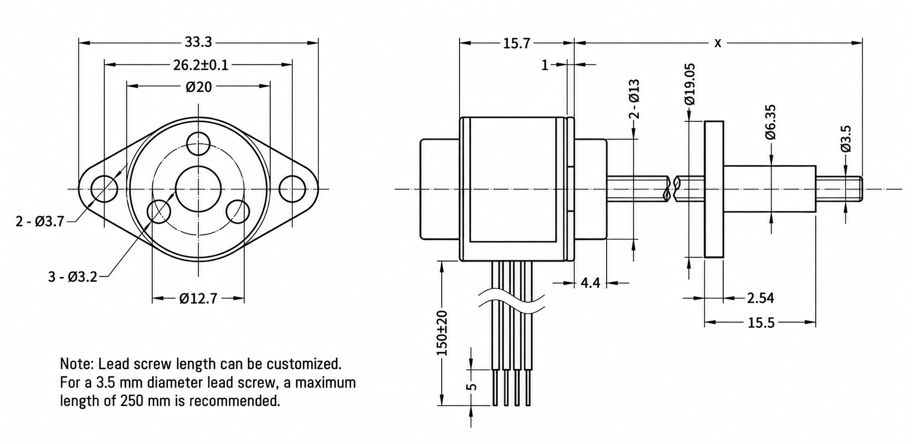
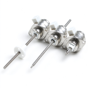
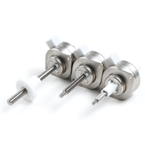
1. Fixed-shaft type; available in two external dimension options.
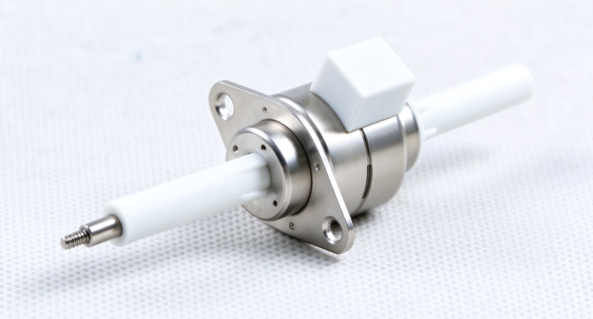
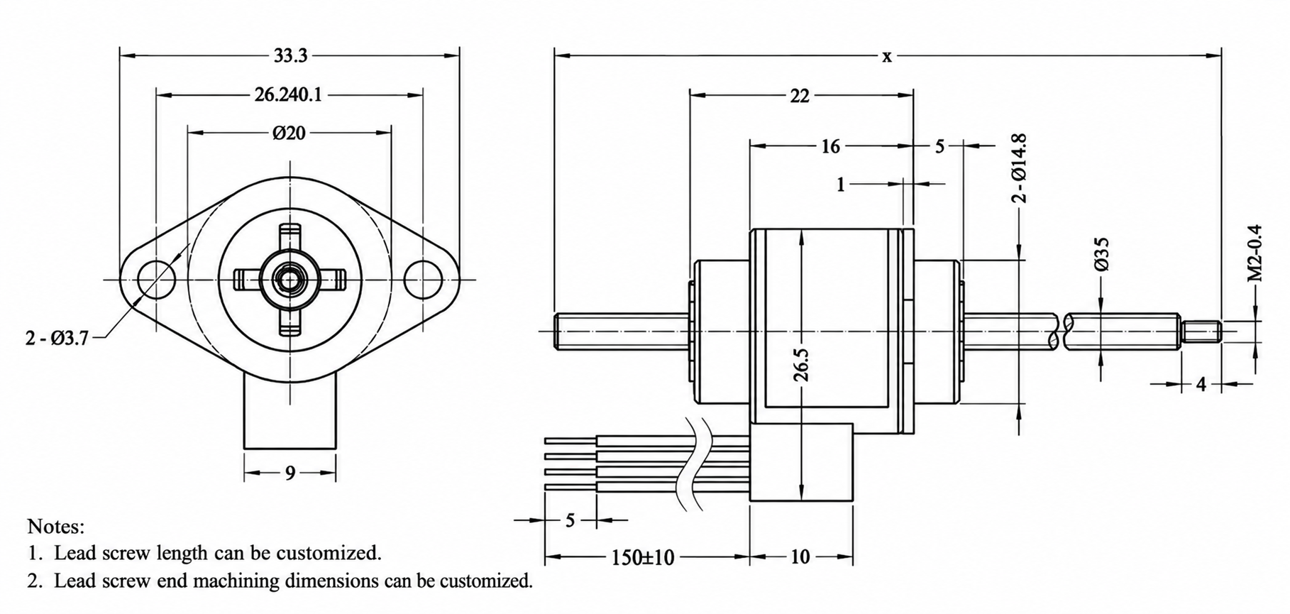
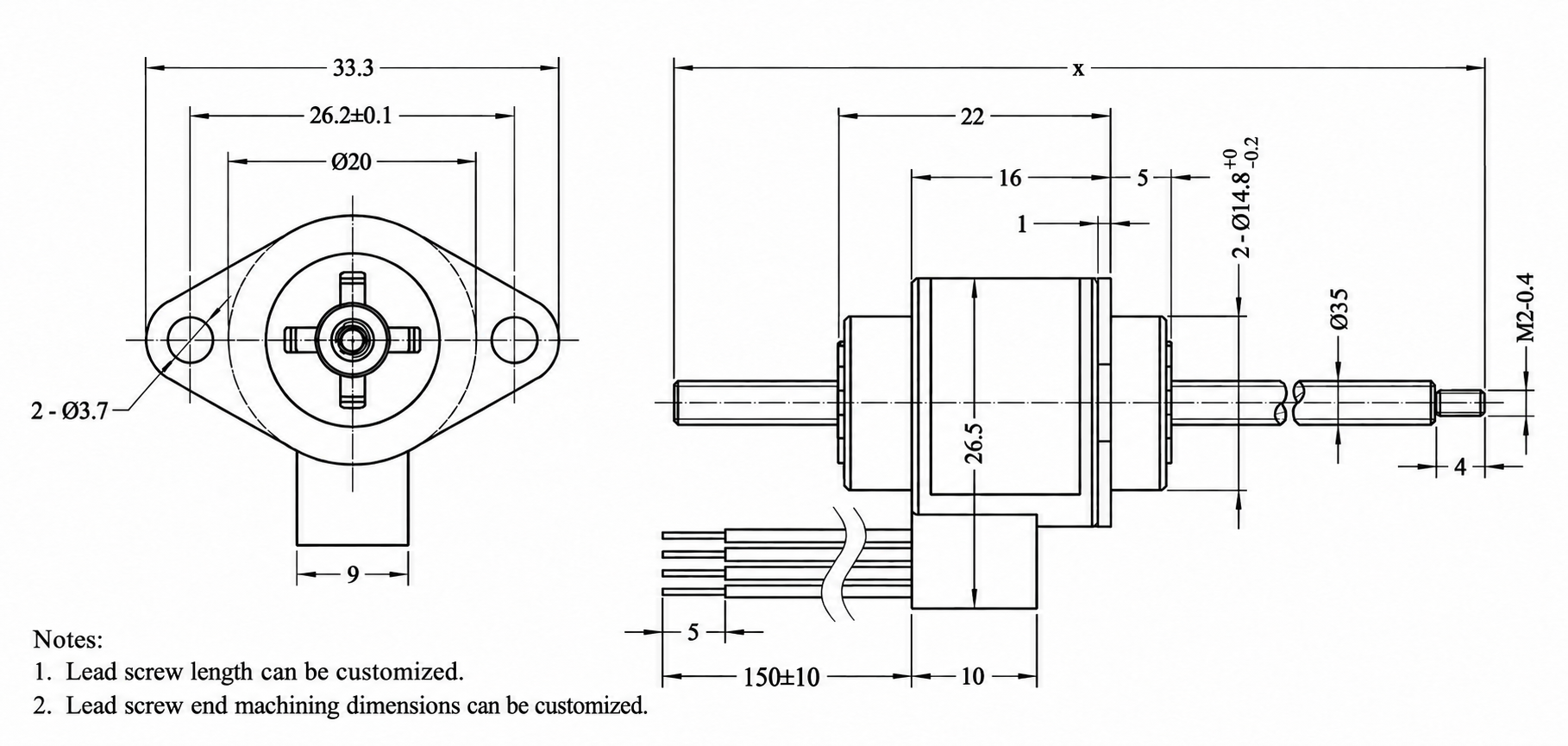
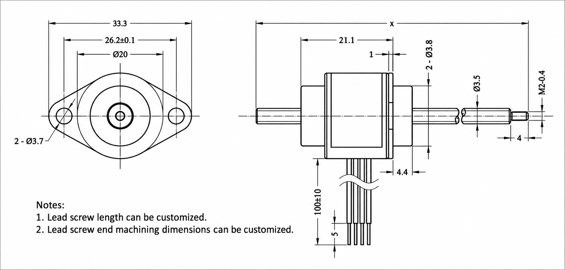
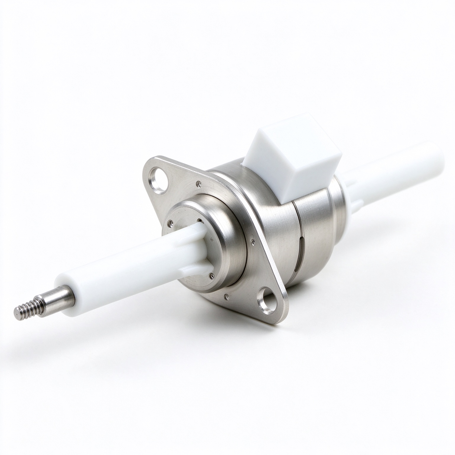
2. Through-shaft type; three external dimension options available.
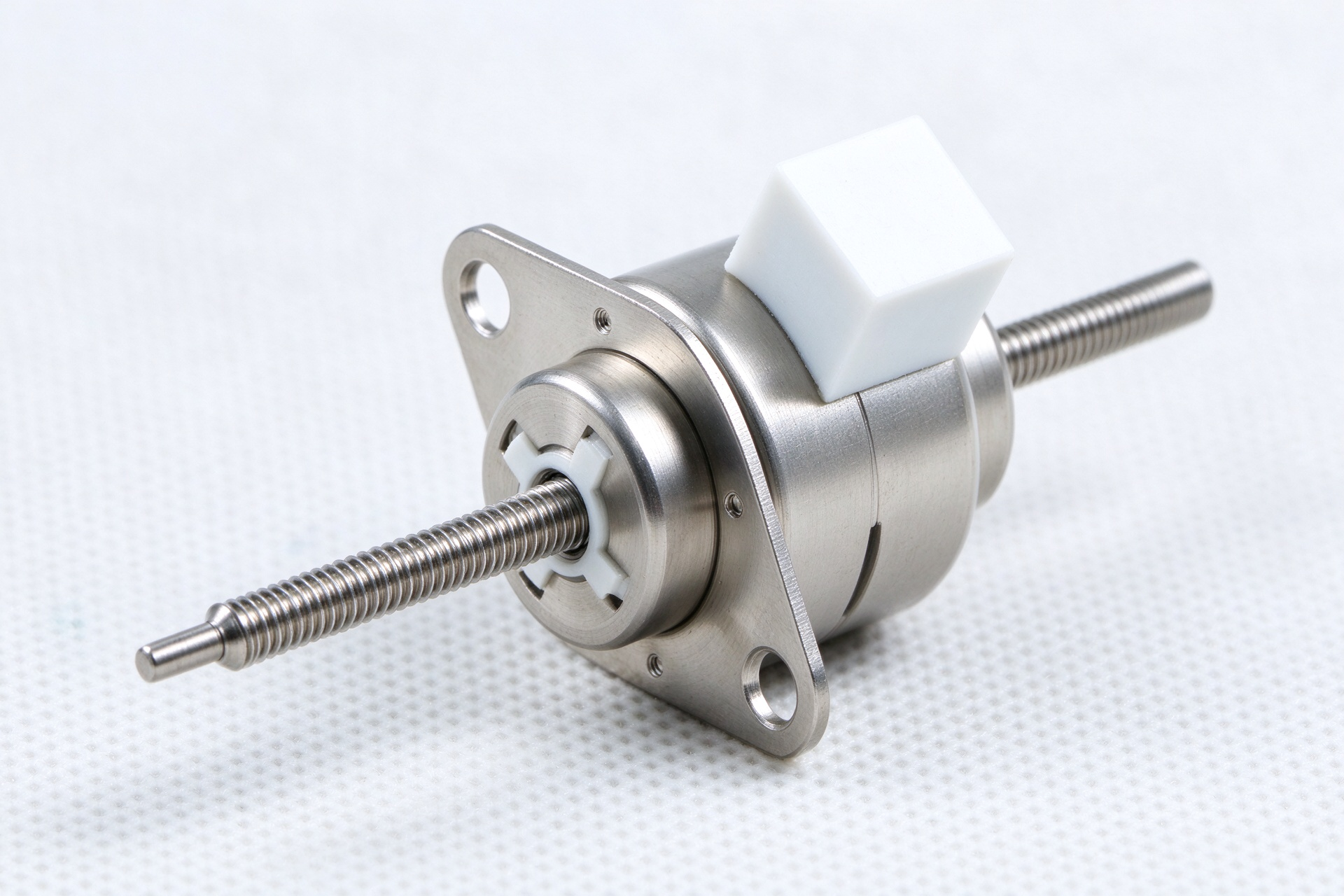
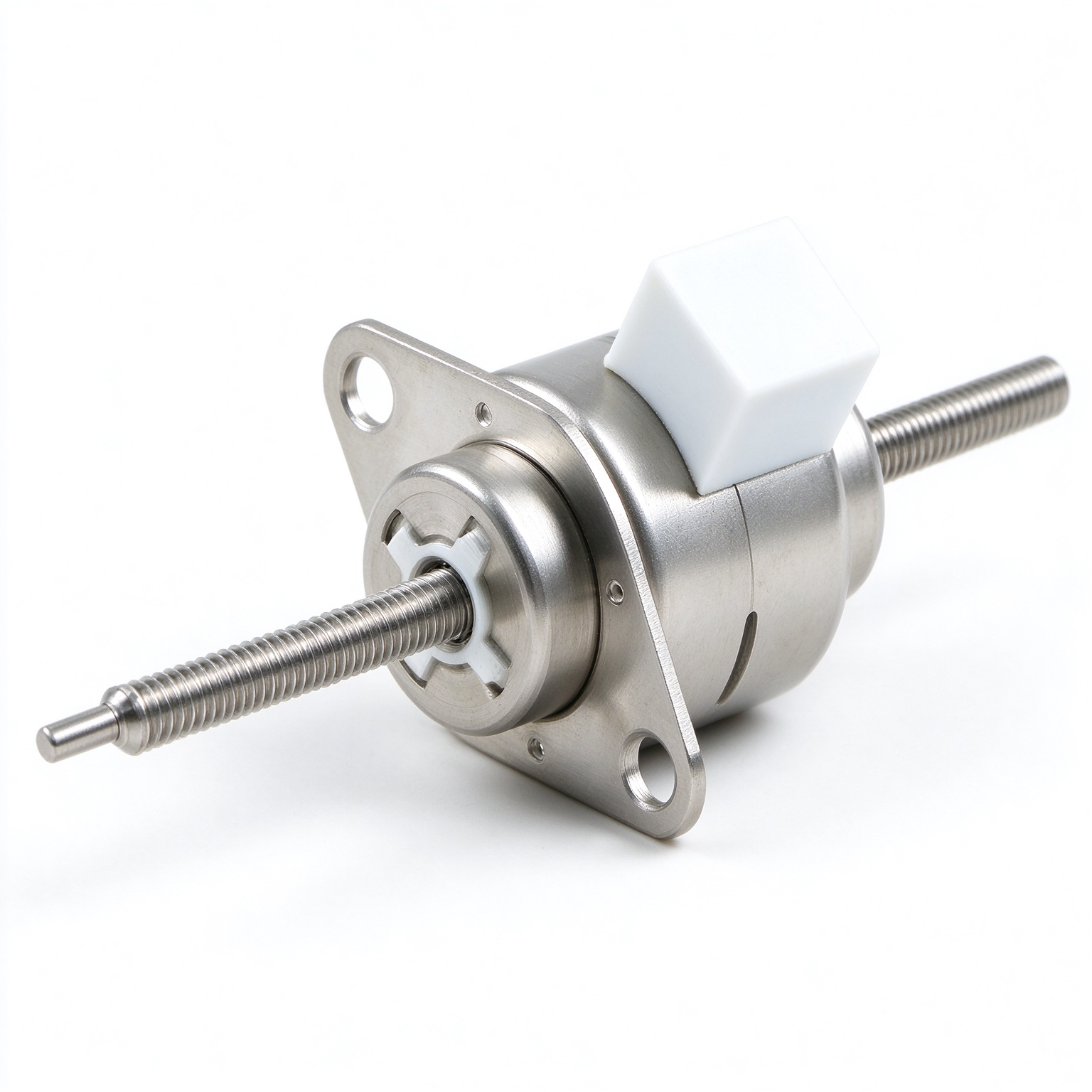
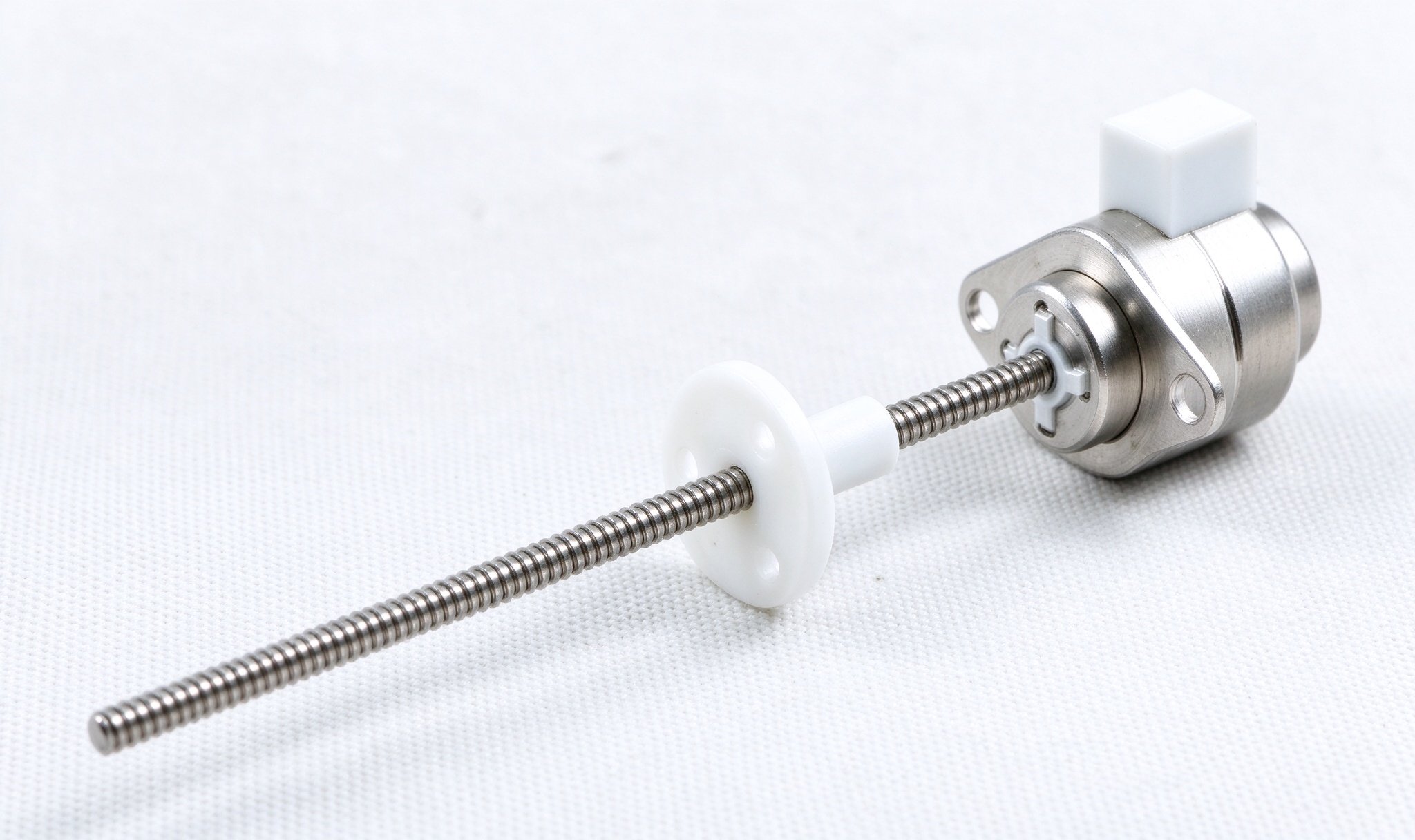
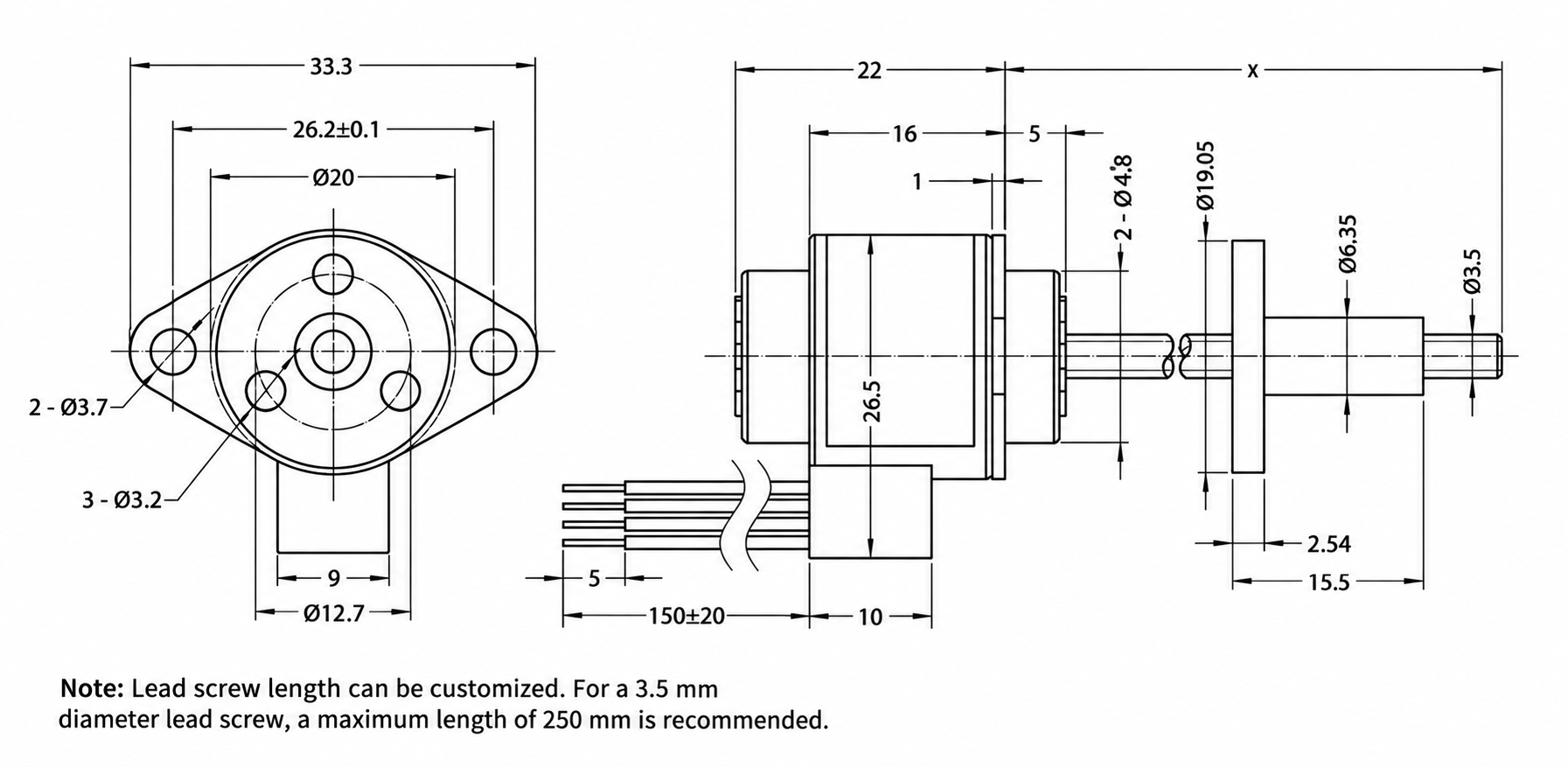
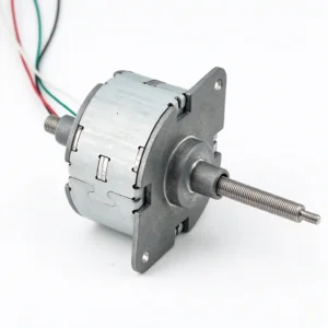
3. External drive type: Two external dimension options are available.
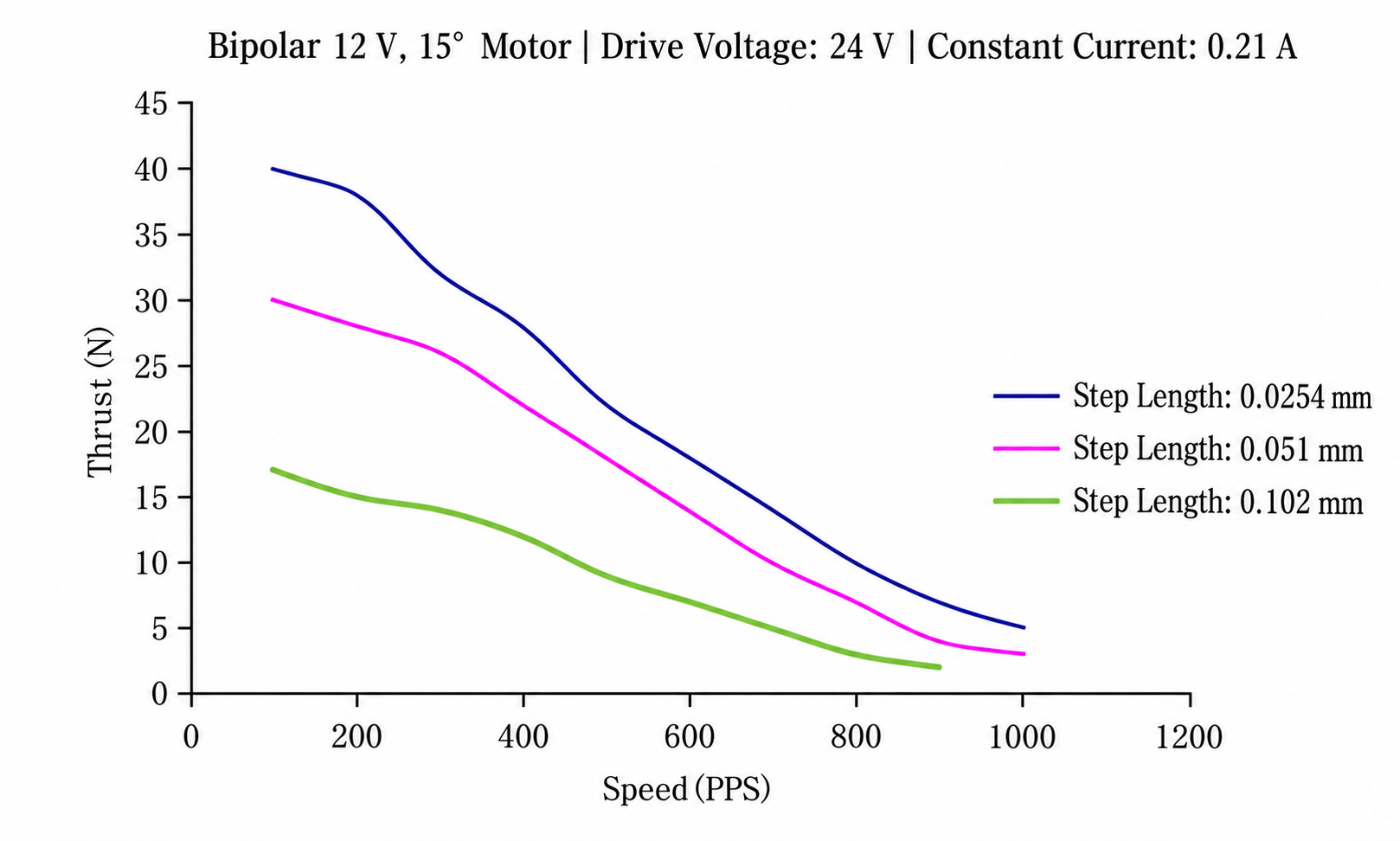
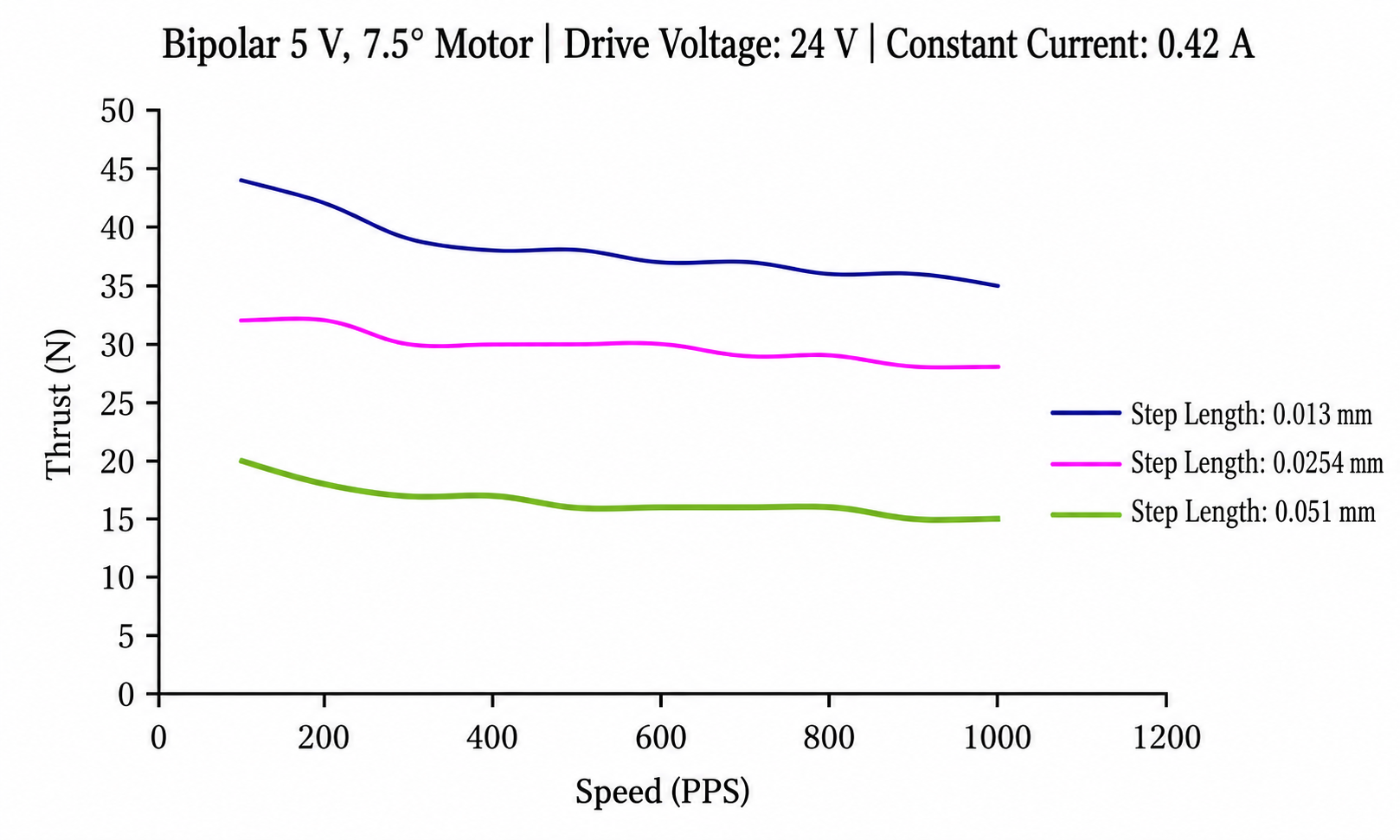
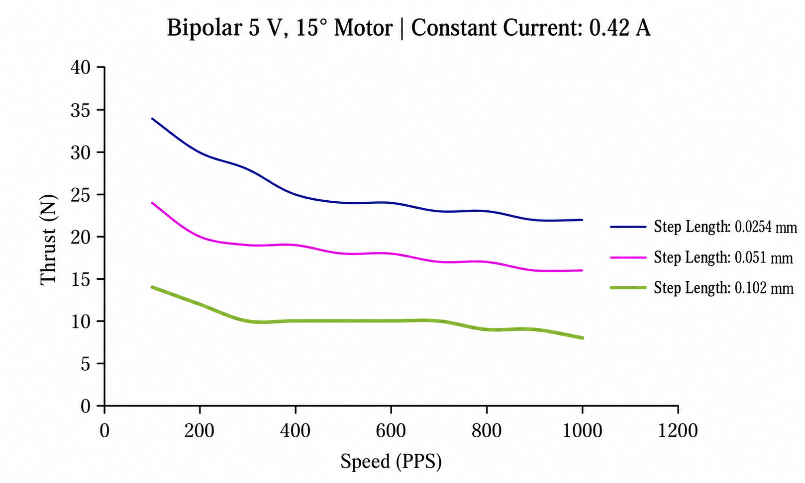
Step speed and thrust curve
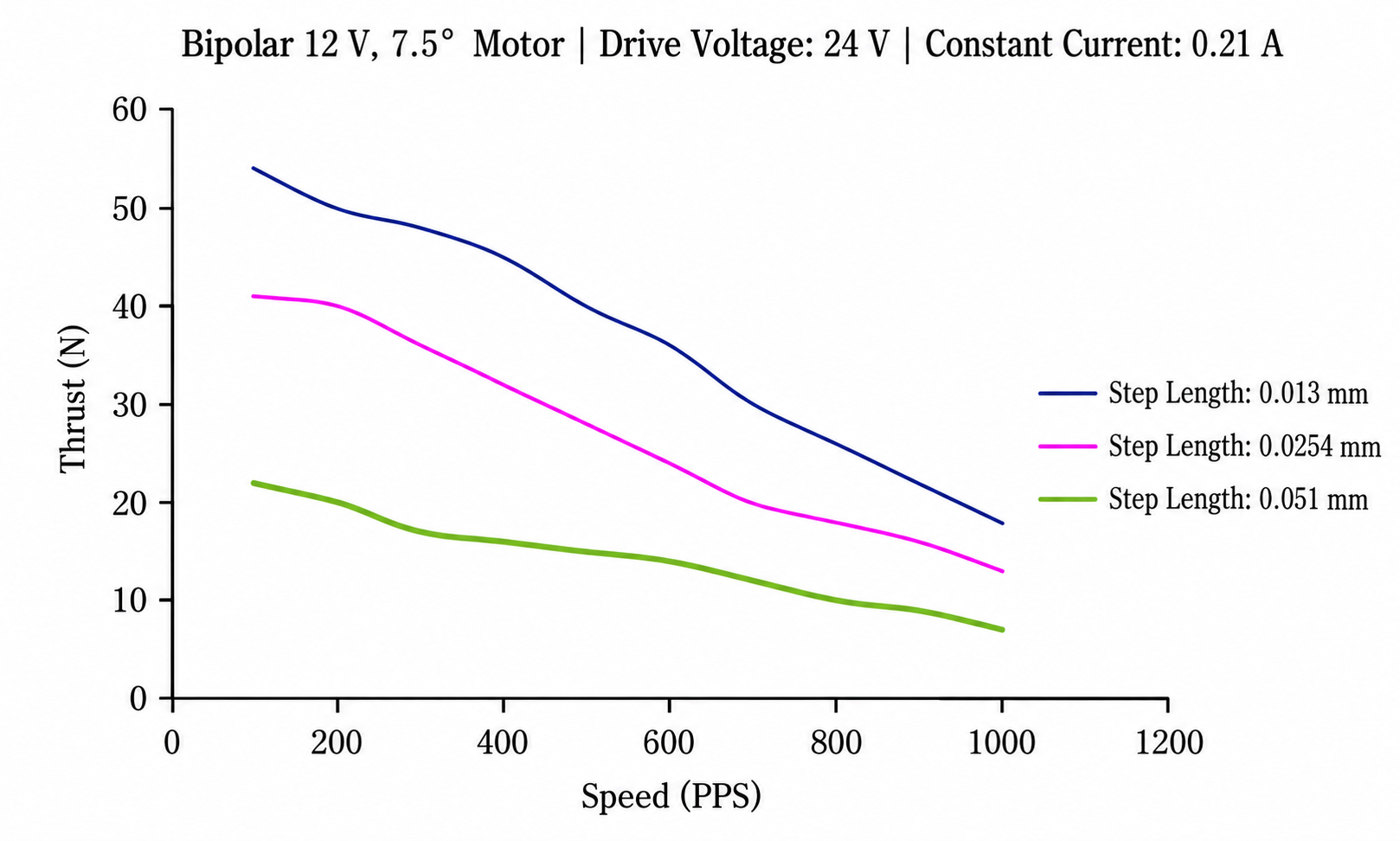
Product Overview
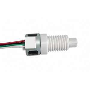
The φ20 Series uses permanent magnet stepper technology to drive a linear transmission. Sequential winding excitation creates stepping motion, while the screw-and-nut arrangement converts that motion into linear displacement.
This combination can simplify small positioning assemblies by bringing the motor and linear drive together. The surrounding equipment must provide any additional guidance, load support, and travel protection required by the chosen design.
Movement per step depends on the motor step angle and screw lead. Actual positioning performance also depends on backlash, alignment, friction, and the motor’s ability to complete each commanded step.
Key Features
Incremental Linear Travel
A compatible controller commands movement through successive steps. This supports mechanisms that require repeated adjustments or movement between selected positions along an axis.
Permanent Magnet Stepping Principle
The rotor’s permanent magnet interacts with magnetic fields generated by the energized windings. Controlled excitation provides the motion needed to operate the linear transmission.
Advancing and Retracting Movement
The appropriate drive sequence enables movement in both directions. This capability suits mechanisms that extend, withdraw, or adjust back and forth during operation.
Integrated Motor and Linear Transmission
Combining the motor with a matching screw-drive arrangement offers a practical starting point for actuator design. Configuration selection should account for which component rotates and which component travels.
Programmable Operating Cycles
A suitable controller can manage movement, pauses, acceleration, and direction changes. Reference switches and sensors can supplement these commands where the equipment needs position confirmation.
Potential Applications
Depending on the selected version and confirmed operating capabilities, the φ20 Series may suit:
- Instrument Adjustment: Positioning guides, stops, and adjustable internal components.
- Optical Assemblies: Moving compatible focusing or alignment mechanisms.
- Guided Linear Actuators: Advancing and retracting components along a supported axis.
- Automation Devices: Performing repeated linear movements within a programmed sequence.
- Appliance Mechanisms: Adjusting internal components during equipment operation.
Guidance and Mechanical Support
Linear guidance helps maintain alignment between the moving component and the drive axis. Depending on the configuration, an anti-rotation feature may be necessary to prevent the screw or nut from rotating unintentionally.
The guide structure should carry side loads and bending forces that the actuator cannot accommodate. Proper support helps prevent binding and unnecessary wear within the screw-and-nut mechanism.
Check clearance throughout the entire movement range. Suitable travel limits should prevent overtravel, collision, or disengagement of the drive components.
Positioning and Control
Step commands define the requested movement, but they do not independently verify actual travel. Applications requiring a known reference position can use a home switch, while additional feedback can confirm displacement.
Acceleration and deceleration settings should match the moving mass and load resistance. Abrupt starts or reversals can increase thrust demand and cause missed steps.
For reversing mechanisms, consider backlash when evaluating positional repeatability. Screw lead accuracy, mounting rigidity, and guide alignment also affect the final result.
Driver and Electrical Matching
Select a driver that matches the chosen motor’s winding configuration and electrical requirements. Confirm the connection diagram and excitation sequence before operation.
Evaluate temperature rise across the full operating cycle, including periods of energized standstill. Holding a load under power can generate heat even when the mechanism remains stationary.
Protect wiring from moving components and repeated mechanical strain. Where cables move with the assembly, provide routing that accommodates the complete travel range.
Installation and Application Selection
Verify the mounting interface, screw geometry, moving component connection, and available space against the product drawing. Maintain alignment during assembly without forcing components into position.
Evaluate the required thrust, travel speed, stroke, positioning needs, and duty cycle together. Include friction, load variation, and installation orientation when assessing the complete mechanism.
Testing the selected φ20 Series motor within the intended equipment helps assess starting behavior, movement consistency, temperature rise, and compatibility with the control system.

Reviews
There are no reviews yet.