
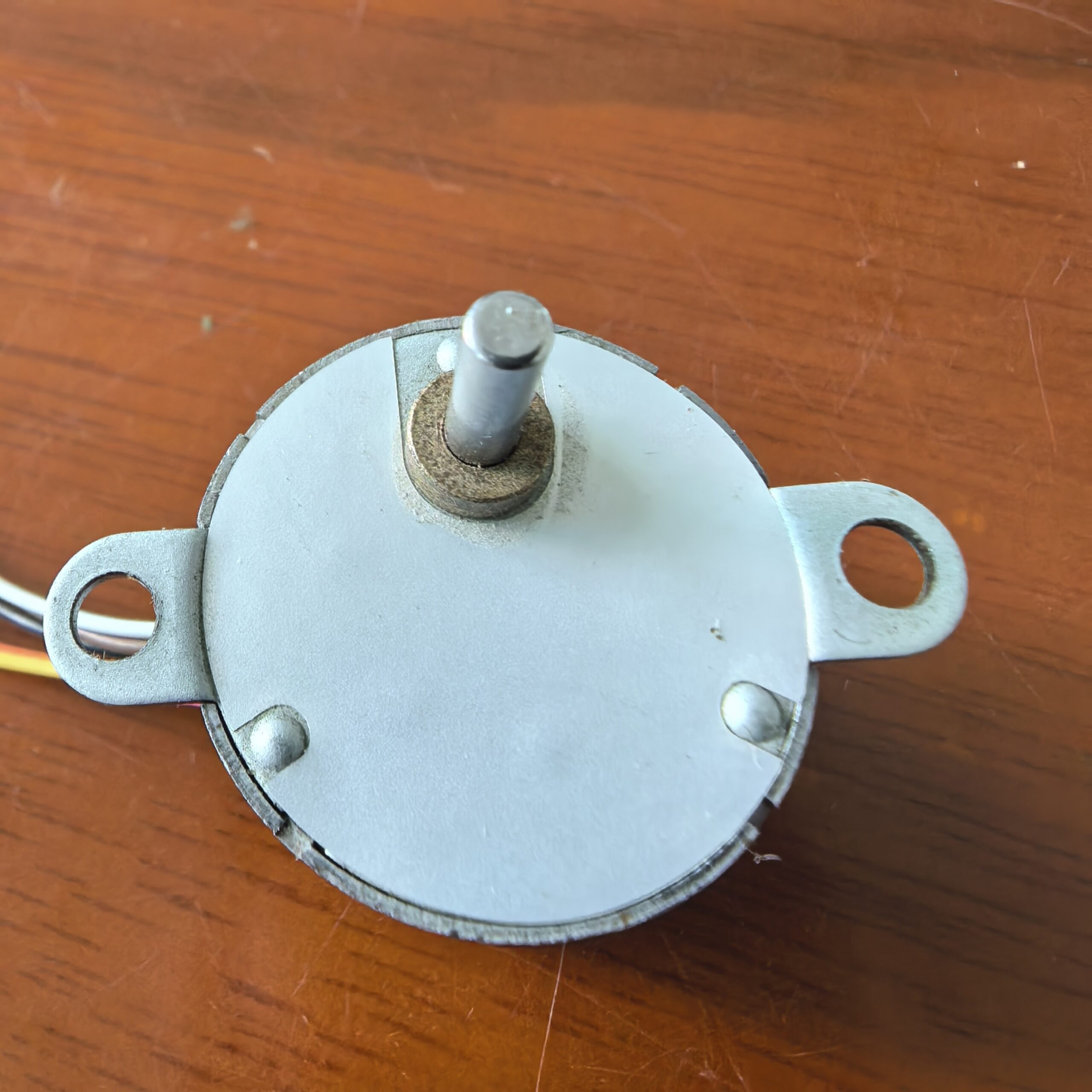
Description
Product Overview
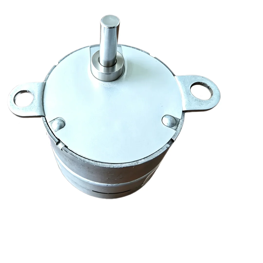
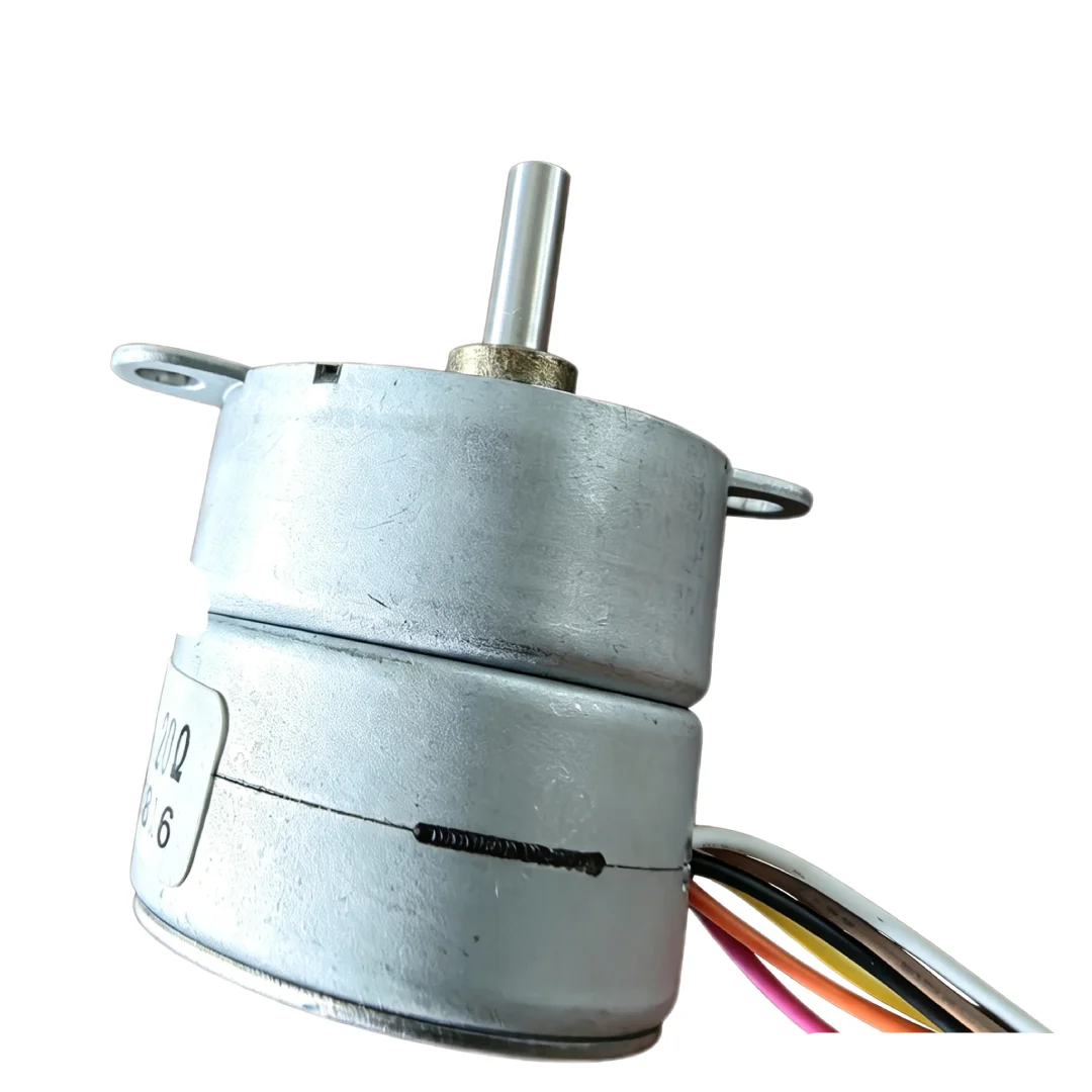
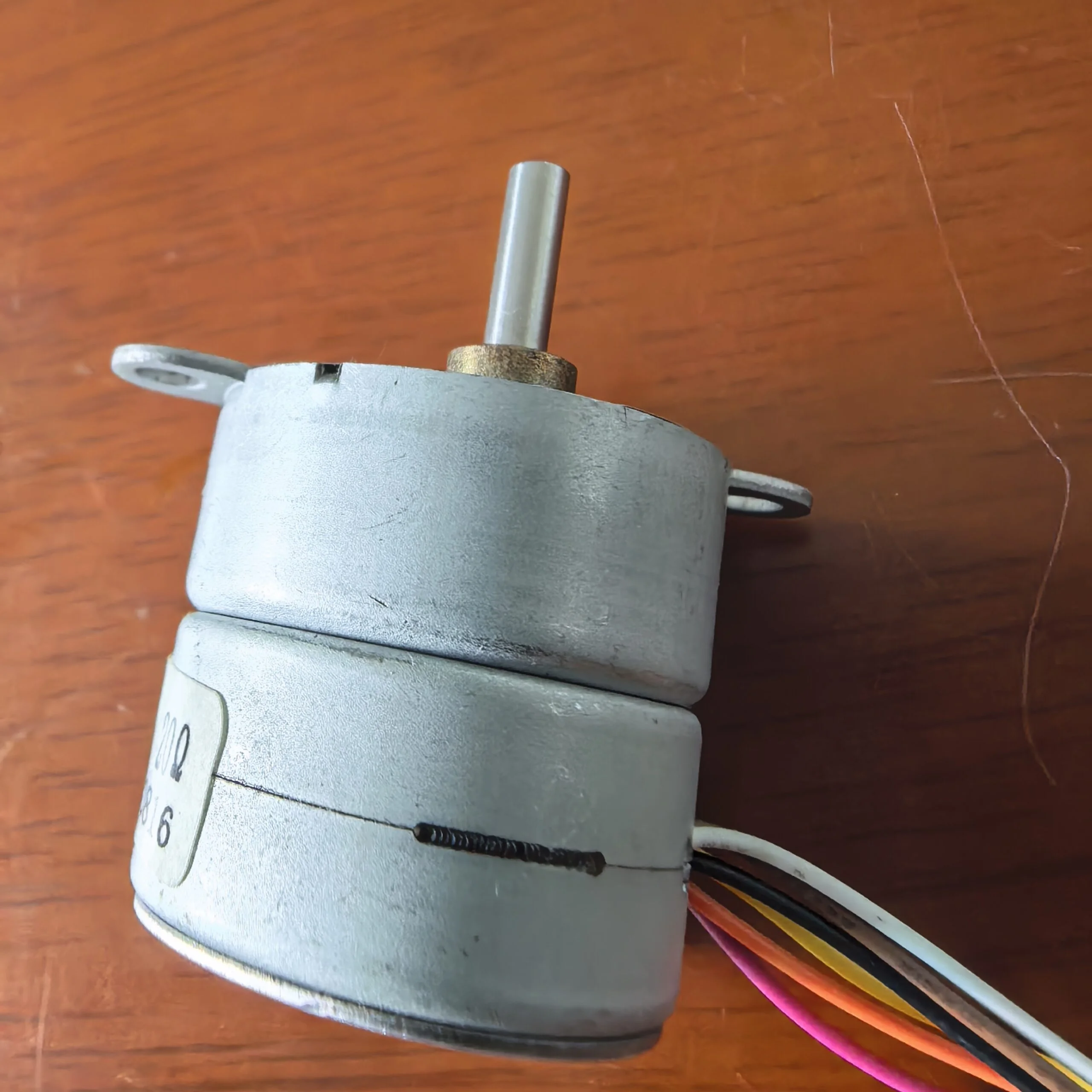
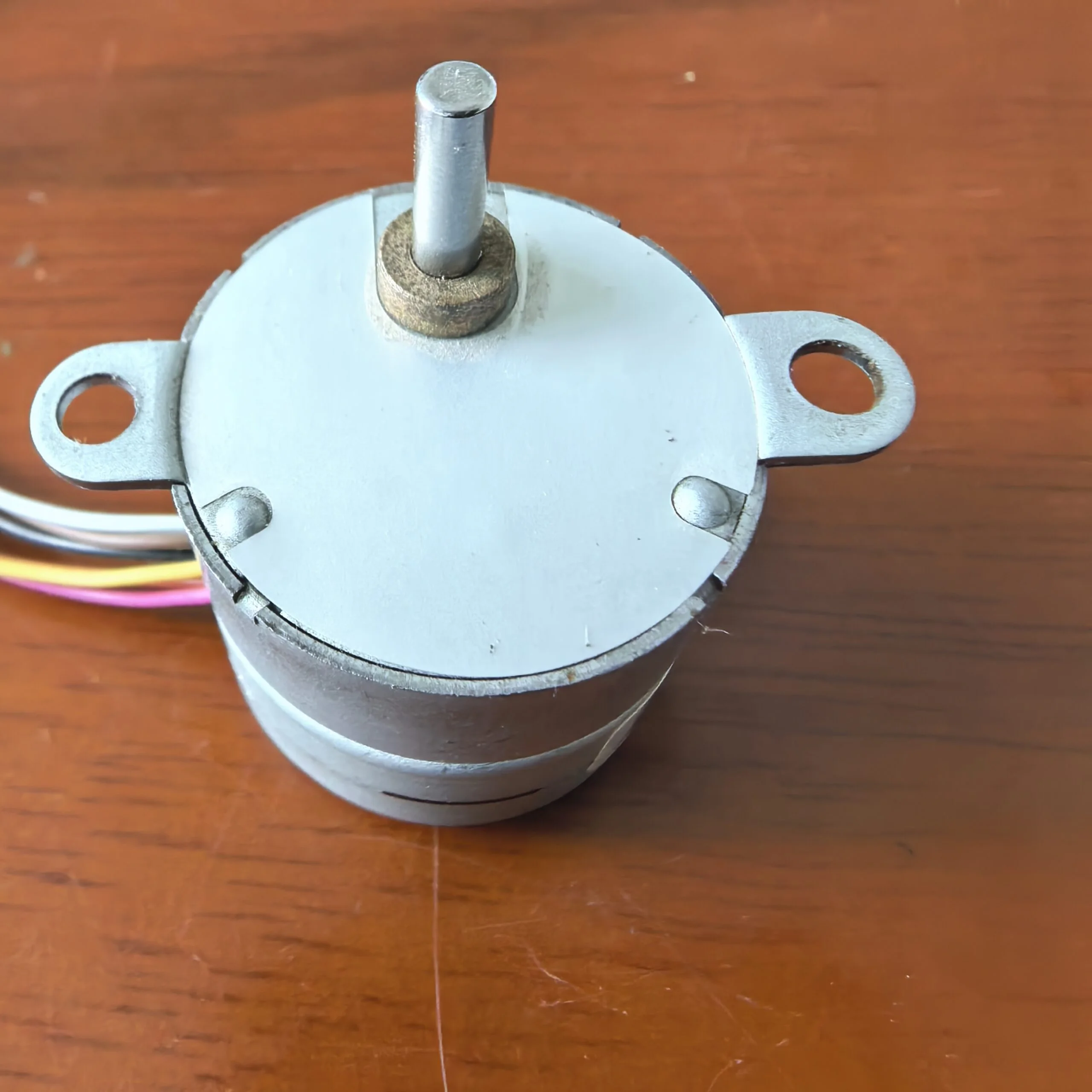
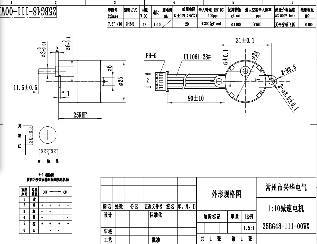
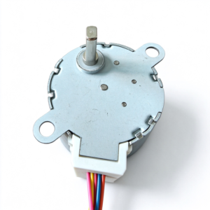
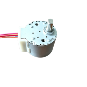
The 25BG48 uses permanent magnet stepper technology to translate electrical drive sequences into shaft rotation. The controller determines the movement sequence, while the driver supplies the winding current needed for operation.
This operating principle allows designers to manage movement through step commands. It can support mechanisms that perform repeated adjustments or move between defined positions.
Successful integration requires matching the motor to the mechanical load and operating cycle. Driver selection, acceleration settings, and shaft alignment all contribute to consistent performance.
Key Features
Permanent Magnet Rotor Design
The rotor incorporates a permanent magnet that interacts with the magnetic fields generated by the stator windings. Sequential excitation moves the rotor through successive angular positions.
Incremental Rotary Movement
Step-based operation allows the control system to command movement in discrete increments. This provides a practical approach to controlling adjustment mechanisms and positioning assemblies.
Forward and Reverse Operation
A compatible drive sequence allows rotation in either direction. This capability supports mechanisms that need opening and closing, advancing and returning, or clockwise and counterclockwise adjustment.
Adjustable Motion Profiles
A suitable controller can manage starting, acceleration, running, and deceleration. Matching the motion profile to the load helps reduce abrupt movement and the risk of missed steps.
Integration with Mechanical Transmissions
Depending on the assembly design, the motor can work with compatible couplings, gears, or other transmission components. The chosen transmission determines how shaft rotation reaches the driven mechanism.
Potential Applications
The 25BG48 Permanent Magnet Stepper Motor may suit the following applications, subject to the selected configuration and operating requirements:
- Instrument Adjustment: Rotary mechanisms that change settings or component positions.
- Appliance Mechanisms: Controlled movement within household or commercial equipment.
- Positioning Assemblies: Mechanisms that move between defined operating positions.
- Automation Devices: Repeated adjustment and actuation within a coordinated control sequence.
- Display Mechanisms: Movement of indicators or other lightweight mechanical elements.
Control and Operation
The motor requires a driver compatible with its winding arrangement and electrical requirements. The control system must use the correct excitation sequence to produce the intended direction and movement.
For applications with changing loads, suitable acceleration and deceleration settings help maintain operation within the available torque range. Positioning performance also depends on transmission backlash, friction, and mechanical rigidity.
Where the equipment requires position verification, a reference switch or feedback device can help establish or confirm the mechanism’s position.
Installation and Integration
Align the motor shaft with the driven component to avoid unnecessary mechanical stress. Use a suitable mounting structure and keep wiring clear of rotating parts.
The coupling and transmission should accommodate the intended load without placing excessive force on the shaft. The equipment design should also provide appropriate heat dissipation and protection from the operating environment.
Motor Selection Considerations
Selection should account for the required movement, available installation space, load characteristics, and operating cycle. The driver, power supply, and control method should match the selected motor configuration.
Evaluating the complete mechanism helps establish suitable starting behavior, operating speed, and positioning performance. This approach supports dependable integration of the 25BG48 into the finished equipment.

Reviews
There are no reviews yet.