
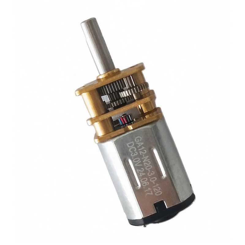
Description
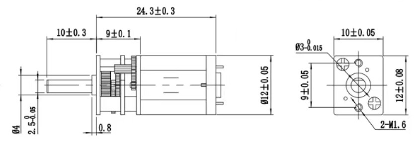
| Parameter | Specification |
|---|---|
| Brush Type | Precious Metal Brushes |
| Bearing Type | Oil-Impregnated Bearings |
| Number of Commutator Segments | 3 |
| Number of Pole Pairs | 1 |
| Connection Type | Terminals |
GA12-N20-3.0-15
| Parameter | Unit | Specification |
|---|---|---|
| Rated Voltage | V DC | 3 |
| No-Load Motor Speed | rpm | 4470 |
| No-Load Motor Current | A | 0.015 |
| Motor Speed Constant | rpm/V | 1490 |
| Gear Reduction Ratio | — | 1:298 |
| Rated Gearbox Output Speed | rpm | 15 |
| Stall Current | A | 0.072 |
| Stall Torque | mN·m | 0.45 |
| Terminal Resistance | Ω | 40.0 |
| Ambient Temperature | °C | −30 to +65 |
| Maximum Permissible Winding Temperature | °C | +80 |
| Noise Level | dB | ≤45 |
GA12-N20-3.0-30
| Parameter | Unit | Specification |
|---|---|---|
| Rated Voltage | V DC | 3 |
| No-Load Motor Speed | rpm | 8940 |
| No-Load Motor Current | A | 0.030 |
| Motor Speed Constant | rpm/V | 2980 |
| Gear Reduction Ratio | — | 1:298 |
| Rated Gearbox Output Speed | rpm | 30 |
| Stall Current | A | 0.350 |
| Stall Torque | mN·m | 1.10 |
| Terminal Resistance | Ω | 8.0 |
| Ambient Temperature | °C | −30 to +65 |
| Maximum Permissible Winding Temperature | °C | +80 |
| Noise Level | dB | ≤45 |
GA12-N20-3.0-120
| Parameter | Unit | Specification |
|---|---|---|
| Rated Voltage | V DC | 3 |
| No-Load Motor Speed | rpm | 6000 |
| No-Load Motor Current | A | 0.015 |
| Motor Speed Constant | rpm/V | 2000 |
| Gear Reduction Ratio | — | 1:50 |
| Rated Gearbox Output Speed | rpm | 120 |
| Stall Current | A | 0.139 |
| Stall Torque | mN·m | 0.20 |
| Terminal Resistance | Ω | 23.0 |
| Ambient Temperature | °C | −30 to +65 |
| Maximum Permissible Winding Temperature | °C | +80 |
| Noise Level | dB | ≤45 |
Product Overview
The brushed DC motor converts electrical energy into rotation through its magnetic field, brushes, and commutator. The gearbox transfers this rotation to the output shaft through a reduction mechanism.
Selecting a suitable gear ratio helps match motor operation to the driven equipment. A greater reduction generally provides lower output speed and greater torque multiplication, subject to gearbox efficiency and mechanical limits.
The complete assembly determines practical performance. Motor characteristics, gearbox construction, supply conditions, and the operating load all influence starting behavior and output movement.
Key Features
Integrated Motor and Gearbox
The combined assembly provides motor drive and speed reduction in one unit. This can simplify equipment layouts that would otherwise require a separate motor and transmission.
Reduced Output Speed
The gearbox lowers shaft speed to suit mechanisms that require slower movement. The appropriate configuration depends on the equipment’s movement rate and operating cycle.
Torque Multiplication
Gear reduction increases available torque at the output relative to the motor shaft, within the assembly’s rated limits. This supports loads that require greater turning force at lower speeds.
Compatible Speed Control
A suitable DC motor controller can adjust operating speed. Actual speed depends on the supply, controller settings, and load; applications requiring closely regulated speed may need feedback.
Direction Control Options
Compatible motor versions can support forward and reverse operation with an appropriate controller. Direction changes should account for load inertia and transmission stress.
Potential Applications
Depending on the selected configuration and operating requirements, a DC brushed gear motor may suit:
- Powered Adjustment Mechanisms: Moving guides, selectors, and adjustable equipment components.
- Small Conveyor Systems: Driving compatible belts or rollers within the assembly’s load limits.
- Dispensing Devices: Operating feed mechanisms and rotary delivery components.
- Automated Assemblies: Providing intermittent or continuous movement during programmed equipment cycles.
- Display Equipment: Rotating presentation platforms and movable display elements.
- Mechanical Actuators: Supplying rotary input to suitable screws, gears, and linkages.
Gearbox Selection
Choose the gearbox according to the required output speed, torque, duty cycle, and available installation space. Include transmission efficiency when evaluating the motor’s ability to move the load.
Starting, reversing, and sudden load changes can place greater stress on gears than steady running. The selected assembly should accommodate these conditions throughout the intended operating cycle.
Backlash can affect mechanisms that reverse direction or require accurate positioning. Applications with demanding positioning requirements may need additional sensing or a transmission designed to limit mechanical play.
Electrical Control
Match the power supply and controller to the motor’s electrical requirements. Startup and stall currents can exceed normal running current, so the control system should accommodate the intended operating conditions.
Where appropriate, current limiting and overload protection can help protect the drive assembly. A stalled output shaft can cause rapid heating and excessive mechanical loading.
For timed movement, an external controller can manage operating periods and pauses. For position-based movement, limit switches or feedback devices can help establish travel boundaries and stopping points.
Installation and Maintenance
Mount the gear motor securely and align the output shaft with the driven component. Use a compatible coupling and provide separate support where the mechanism introduces excessive radial or axial loads.
Protect wiring from moving parts and mechanical strain. Allow suitable heat dissipation around the motor housing.
Brushes and the commutator experience wear during operation. Maintenance and replacement needs depend on motor construction, load, operating time, and environmental conditions. Follow the applicable gearbox lubrication requirements.
Application Matching
Evaluate running torque, starting load, output speed, and duty cycle together. Include friction, load inertia, direction changes, and any periods when the mechanism may become obstructed.
Testing the selected gear motor in the intended equipment helps assess movement consistency, temperature rise, noise, and controller performance under representative conditions.

Reviews
There are no reviews yet.