
Description
Product Overview
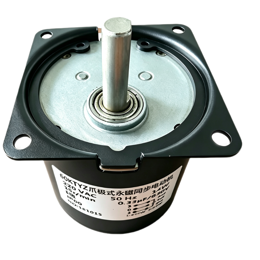
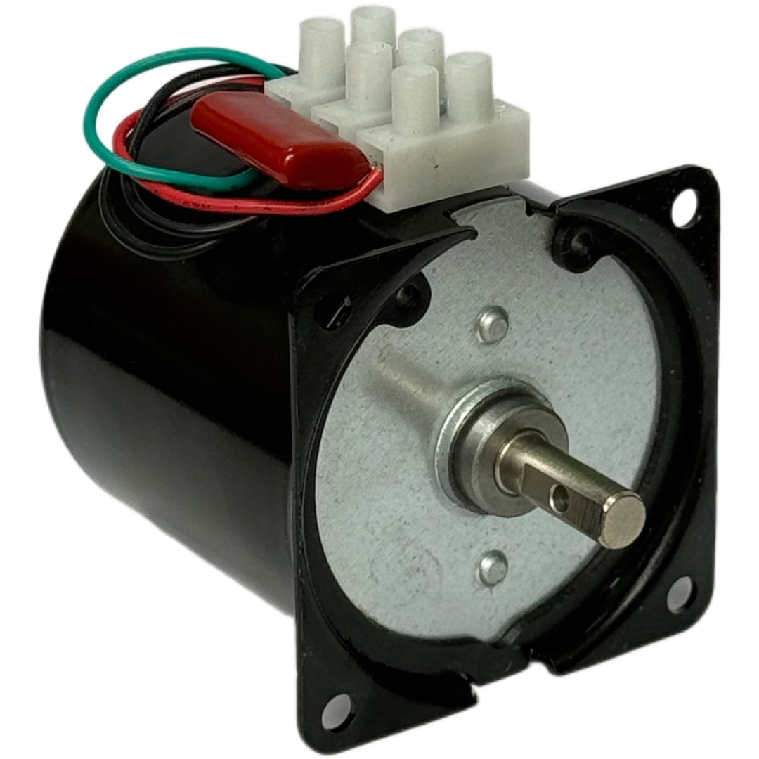
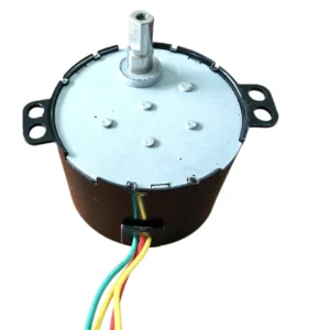
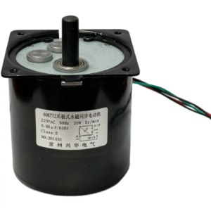
The 60KTYZ uses permanent magnet synchronous technology to produce rotary motion. During synchronous operation, rotor speed follows the supply frequency and the motor’s pole arrangement. Where the selected version includes reduction gearing, the transmission determines the final output speed.
This operating principle suits equipment that requires consistent rotation under a compatible load. An external control system can switch operation according to timers, sensors, or programmed equipment commands.
The complete assembly determines practical performance. Starting resistance, load inertia, transmission friction, and supply conditions all influence how the mechanism starts and runs.
Key Features
Permanent Magnet Synchronous Operation
The permanent magnet rotor interacts with the stator’s rotating magnetic field. Within the motor’s operating capability, this interaction maintains synchronous rotation.
Steady Running Speed
A stable supply frequency supports consistent running speed while the motor remains in synchronism. This characteristic can benefit mechanisms that require uniform rotary movement throughout an operating cycle.
AC Equipment Integration
The motor operates from a compatible AC supply using the connection arrangement specified for the selected version. Correct supply matching and wiring support suitable starting and running behavior.
Timed Rotary Movement
An external controller can manage operating periods and pauses. This allows the motor to participate in equipment cycles that require rotation at selected times.
Mechanical Drive Compatibility
The output shaft can connect to a matching coupling, gear, or linkage. The mounting arrangement and shaft connection should maintain alignment and accommodate the intended load.
| Speed (rpm) | Torque (kgf·cm) |
|---|---|
| 1.2 | 90 |
| 2.5 | 45 |
| 5 | 30 |
| 7.5 | 28 |
| 10 | 24 |
| 15 | 16 |
| 20 | 12 |
| 25 | 10 |
| 30 | 8 |
| 40 | 6 |
| 50 | 4.5 |
| 60 | 4 |
| 80 | 3 |
| 110 | 2.5 |
| Duty Conditions | Operating Cycle |
|---|---|
| Normal torque | Continuous operation for 5–8 hours |
| Higher torque | Run for 30 minutes, then stop for 30 minutes |
| Higher torque, short-duration operation | Run for no more than 5 minutes, then stop for at least 30 minutes |
| Output Shaft Parameter | Specification |
|---|---|
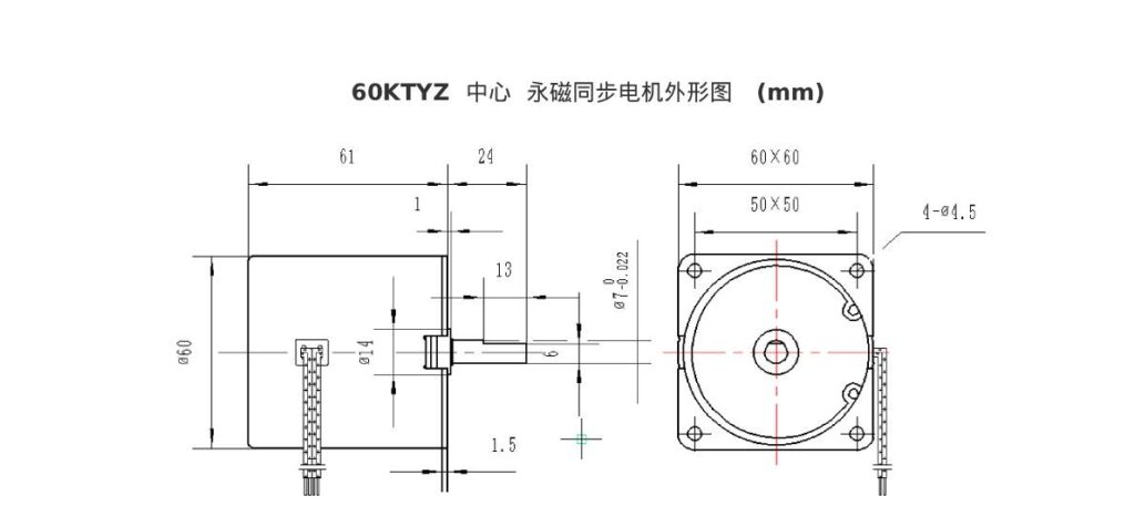
| Maximum Shaft Diameter | Ø8 mm |
| Standard Shaft Dimensions | Ø7 × 19.8 mm; single-flat dimensions: 6.5 × 18 mm |
| Other Shaft Specifications | Custom-made to requirements |
| Eccentric Output Shaft | Custom-made only; not available from stock |
| Eccentric Offset | 10 mm |
Potential Applications
Depending on its confirmed specifications and duty rating, the 60KTYZ Permanent Magnet Synchronous Motor may suit:
- Rotating Display Equipment: Driving presentation platforms and movable display components.
- Appliance Mechanisms: Operating internal assemblies that require steady rotary movement.
- Timed Actuation Devices: Providing rotation during defined operating periods.
- Automated Equipment: Driving compatible mechanisms coordinated with an external control system.
- Instrument Assemblies: Moving components where consistent running speed supports the equipment function.
Rotation Direction and Control
Confirm the rotation characteristics of the selected motor version before integration. Applications requiring direction changes need a configuration and wiring arrangement that support reversible operation.
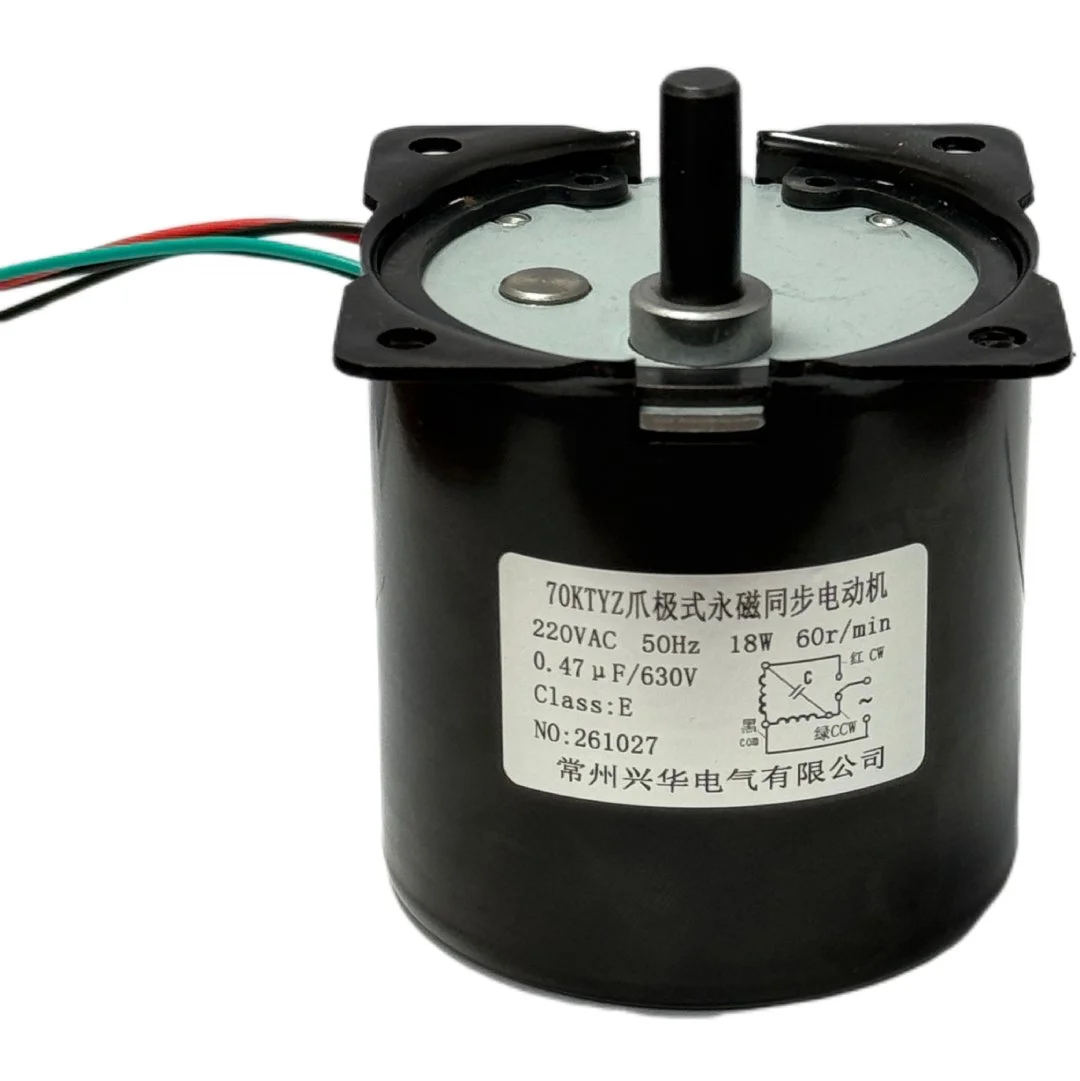
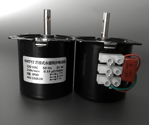
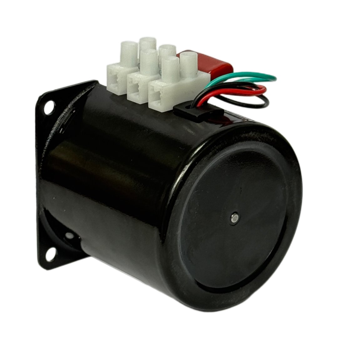
Follow the applicable wiring diagram when connecting the supply and any required external components. Capacitor requirements and connection methods depend on the specific version.
For mechanisms that require defined stopping positions, incorporate appropriate sensing or positioning components. Synchronous running speed does not independently confirm the position of the driven assembly.
Installation Considerations
Mount the motor securely on a surface that maintains alignment during operation. Check clearance around the housing, output shaft, wiring, and connected transmission.
Use a compatible coupling and avoid excessive axial or radial forces. Provide separate support where the driven assembly requires it.
Protect electrical connections from vibration, pulling, and contact with moving parts. The enclosure should provide suitable heat dissipation and protection for the intended environment.
Selecting the Appropriate Configuration
Evaluate output speed, starting torque, running load, and duty cycle together. Include the resistance the mechanism encounters throughout its movement.
Excessive load can prevent startup or cause the motor to lose synchronism. Test the selected configuration within the intended equipment to assess starting behavior, movement consistency, noise, and temperature rise.

Reviews
There are no reviews yet.