
Description
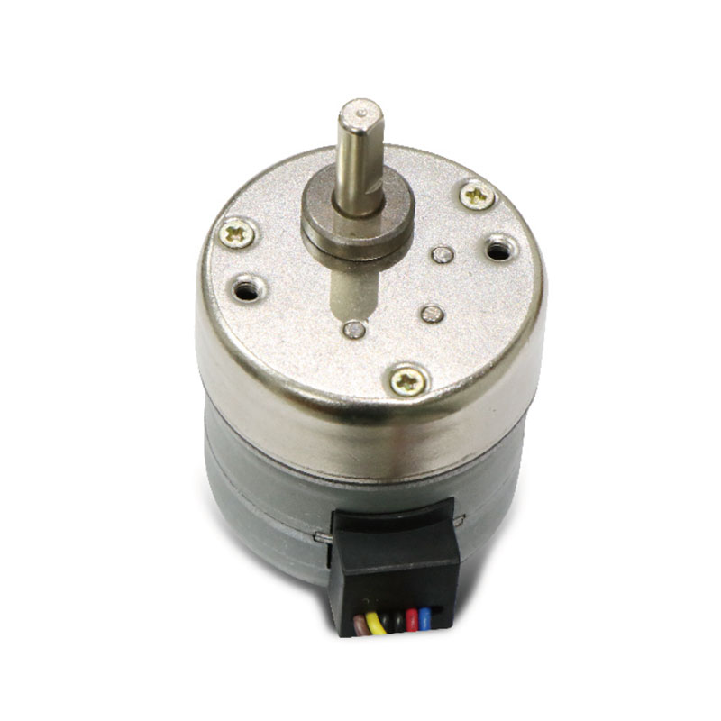
Product Overview
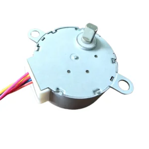
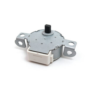
The 35BG uses sequential winding excitation to move the rotor between successive angular positions. A suitable driver supplies winding power, while the controller manages the sequence and timing of movement commands.
This operating principle allows designers to control rotary movement through step commands. The motor can perform repeated adjustments, advance a mechanism, or reverse direction as part of an equipment cycle.
Application performance depends on the selected motor configuration and the complete mechanical assembly. Load inertia, friction, transmission backlash, and driver settings all influence the resulting movement.
Key Features
Permanent Magnet Rotor Construction
The rotor incorporates permanent magnets that interact with the stator’s electromagnetic fields. Controlled excitation produces the stepping action required for incremental rotation.
Step-Based Movement
The motor responds to a compatible drive sequence with discrete rotary increments. This supports mechanisms that require movement between selected positions or repeated angular adjustments.
Bidirectional Rotation
An appropriate excitation sequence enables clockwise and counterclockwise movement. This capability supports return cycles, alternating adjustments, and mechanisms that operate in both directions.
Programmable Motion
A compatible controller can coordinate starting, stopping, speed changes, and pauses. These functions allow motor movement to follow the needs of the equipment’s operating sequence.
Mechanical Drive Integration
The output shaft can connect to a matching coupling or transmission. Correct alignment and suitable support help transfer movement without imposing unnecessary forces on the motor.
| Parameter | Specification |
|---|---|
| Motor Model | 35BG |
| Steps per Revolution | 48 (7.5°/step) / 24 (15°/step) |
| Step Angle | 7.5° & 15° / 30 |
| Excitation Mode | 2-2 / 1-2 Phase |
| Drive Voltage | 5–24 V |
| Coil Resistance per Phase | Customized to customer requirements |
| Driver IC | L297/298 & SLA7024 |
| Magnet Material | Nd-Fe-B |
| Insulation Resistance | ≥100 MΩ |
| Dielectric Strength | AC 500 V for 1 minute |
| Insulation Class | Class E |
| Operating Temperature | −10°C to +50°C |
| Storage Temperature | −30°C to +80°C |
| Operating Humidity | 20%–90% RH |
Potential Applications
Depending on its confirmed specifications and operating requirements, the 35BG Permanent Magnet Stepper Motor may suit:
- Instrument Adjustment: Moving selectors, indicators, and adjustable internal components.
- Appliance Mechanisms: Operating components during programmed equipment cycles.
- Rotary Positioning Assemblies: Moving compatible mechanisms between defined operating positions.
- Small Automation Devices: Performing repeated movements coordinated with controller commands.
- Actuation Systems: Providing rotary input to suitable gears, linkages, or adjustment mechanisms.
Movement and Position Control
The control system determines the requested movement through the drive sequence. Suitable acceleration and deceleration settings help the motor accommodate the inertia of connected components.
For mechanisms with changing resistance, assess torque demand throughout the full movement range. Abrupt starts or reversals can cause missed steps when the required torque exceeds the available output.
Step commands alone do not confirm the actual shaft position. Applications requiring position verification can incorporate a reference switch or suitable feedback device.
Electrical Integration
Select a driver that matches the motor’s winding arrangement and electrical requirements. Verify the wiring assignments, excitation sequence, and power supply compatibility before operation.
Driver settings should suit the selected motor version and intended duty cycle. Evaluate temperature rise during representative operation, including periods when the motor remains energized at rest.
Keep electrical connections secure and protect the leads from repeated bending, pulling, or contact with moving parts.
Mounting and Assembly
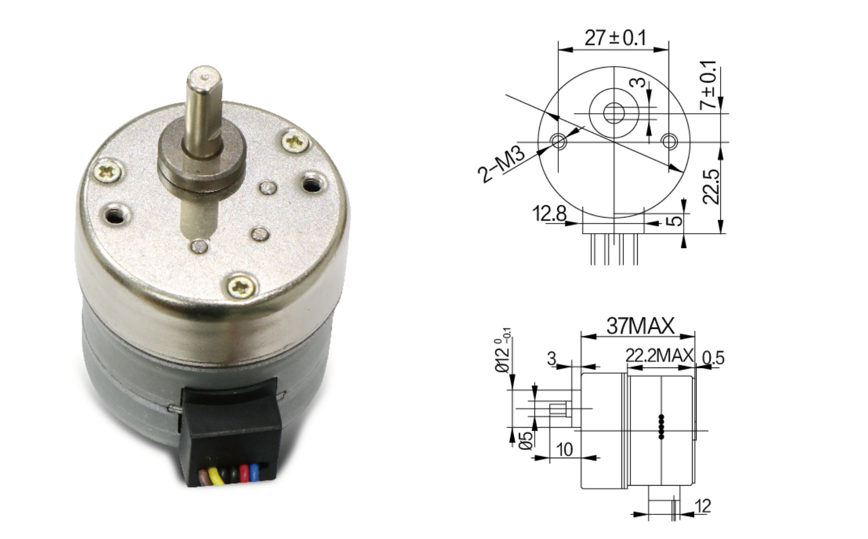
Check the mounting dimensions, shaft geometry, and installation clearance against the product drawing. Secure the motor to a structure that maintains alignment during operation.
Use a compatible coupling and avoid forcing misaligned components together. Provide additional support where the driven mechanism introduces excessive axial or radial loads.
The enclosure should provide appropriate heat dissipation and protection from the operating environment.
Application Selection
Evaluate the required torque, movement speed, positioning needs, and operating cycle together. Include transmission friction, mechanical play, and load variation when selecting the motor configuration.
Testing the 35BG within the intended equipment helps assess starting behavior, direction changes, movement consistency, and temperature rise. These results support suitable driver settings and mechanical integration for the finished assembly.

Reviews
There are no reviews yet.