
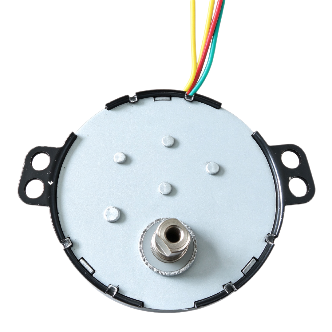
Description
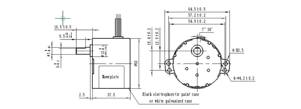
50KTYZ Permanent Magnet Synchronous Motor – Dimensional Drawing (mm)
Product Overview
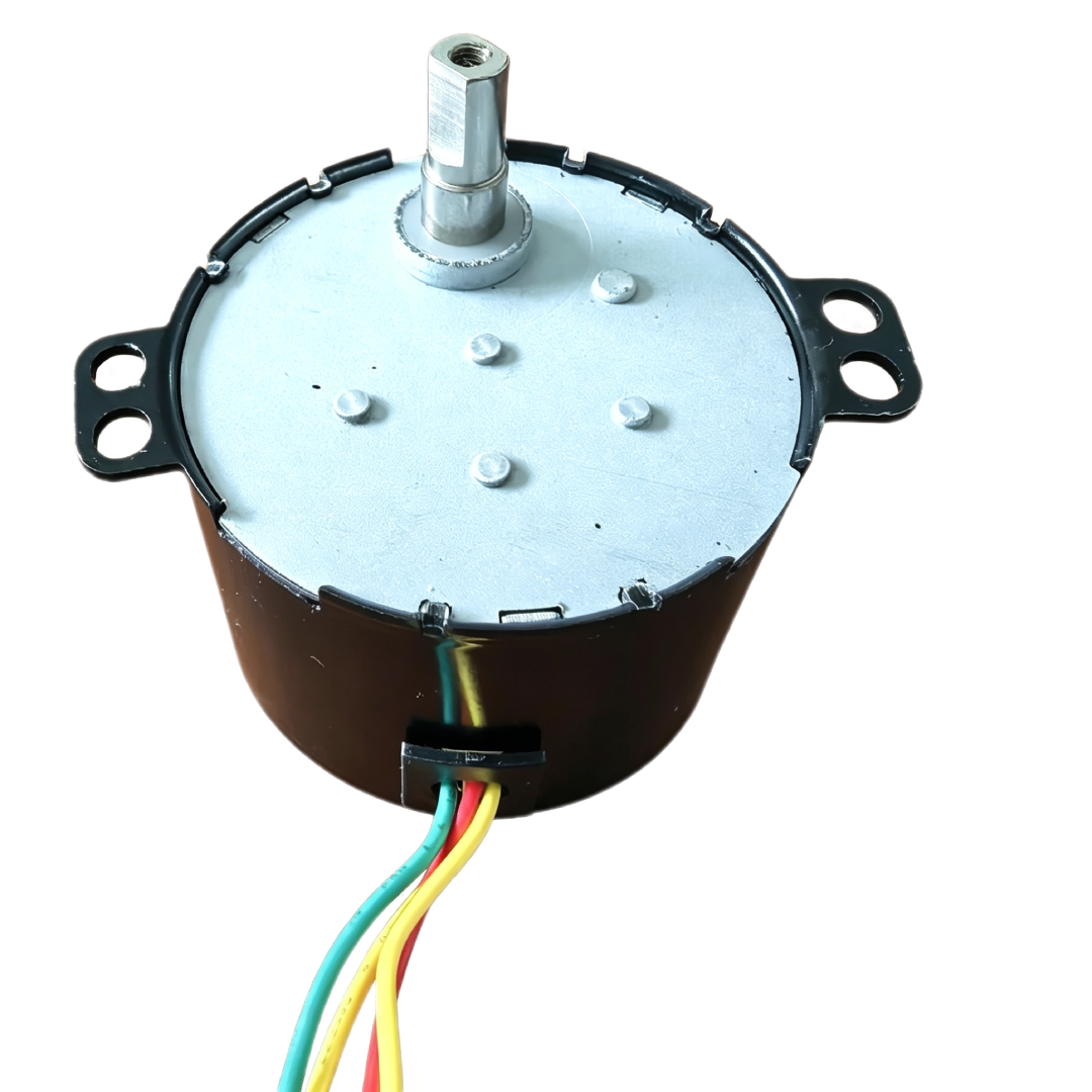
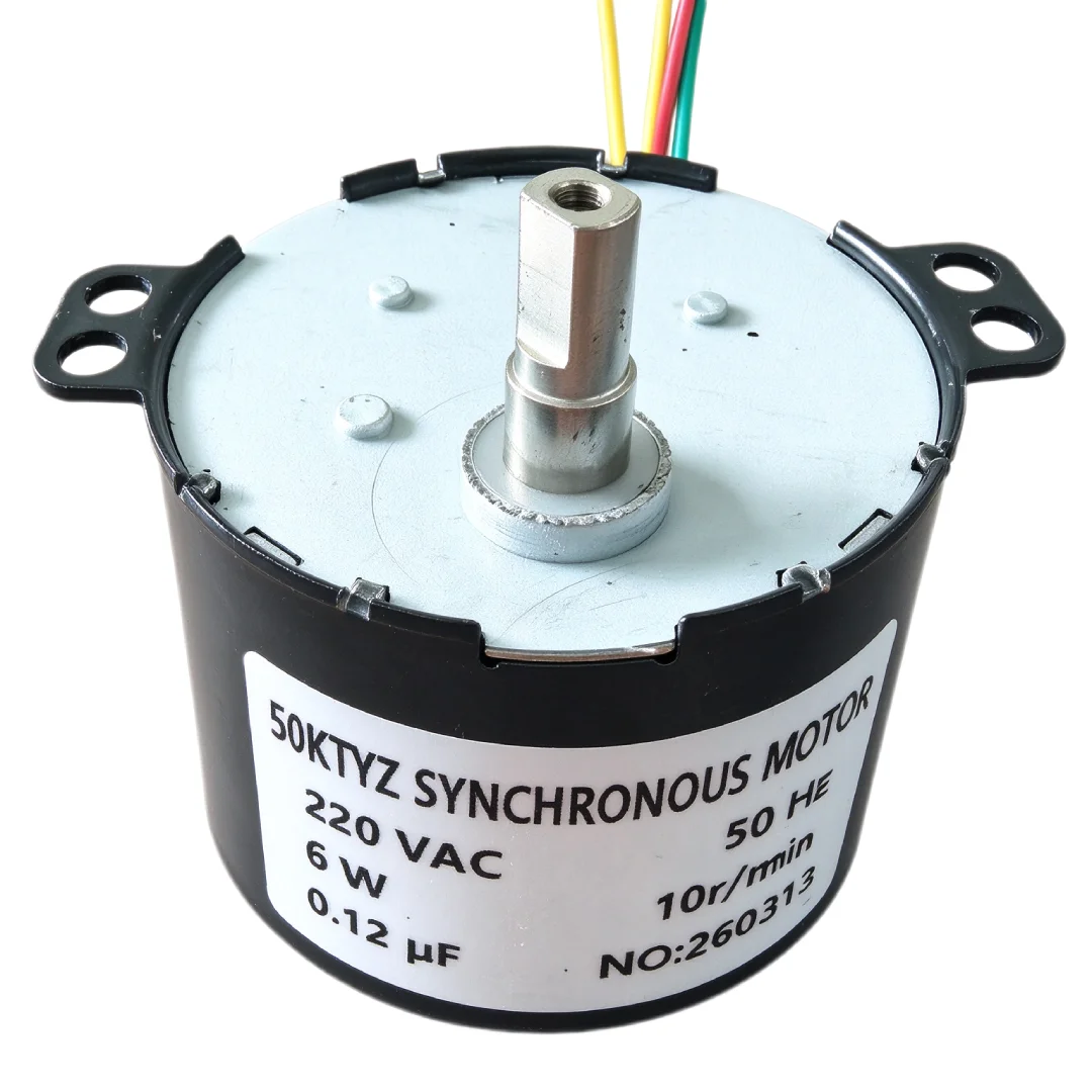
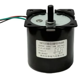
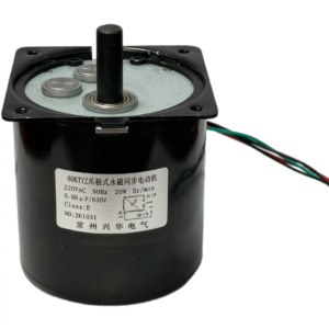
The 50KTYZ offers a drive option for equipment that performs continuous or timed rotary movement. Potential uses include rotating displays, appliance mechanisms, and automated assemblies with compatible load requirements.
Motor selection depends on the required output speed, torque, rotation direction, and operating cycle. Matching these characteristics to the driven mechanism helps maintain synchronous operation under the intended load.
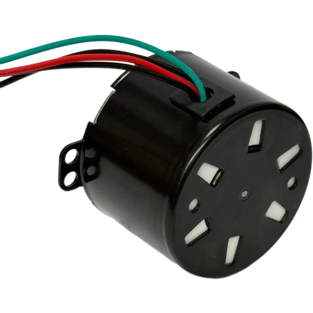
The selected version’s electrical connection and direction characteristics should match the equipment design. Reversible operation requires a motor configuration and wiring arrangement that support it.
Key Features
Permanent Magnet Rotor
The rotor uses permanent magnets to interact with the stator’s rotating magnetic field. Once operating synchronously, it follows that field at the corresponding synchronous speed.
Steady Rotary Operation
At a stable supply frequency and within its operating capability, the motor maintains synchronous rotation. This characteristic suits mechanisms that need consistent movement during an operating cycle.
AC Drive Integration
The motor operates with a compatible AC supply and the connection arrangement specified for the selected version. Correct electrical matching forms the basis for suitable starting and running behavior.
Output Configuration Matching
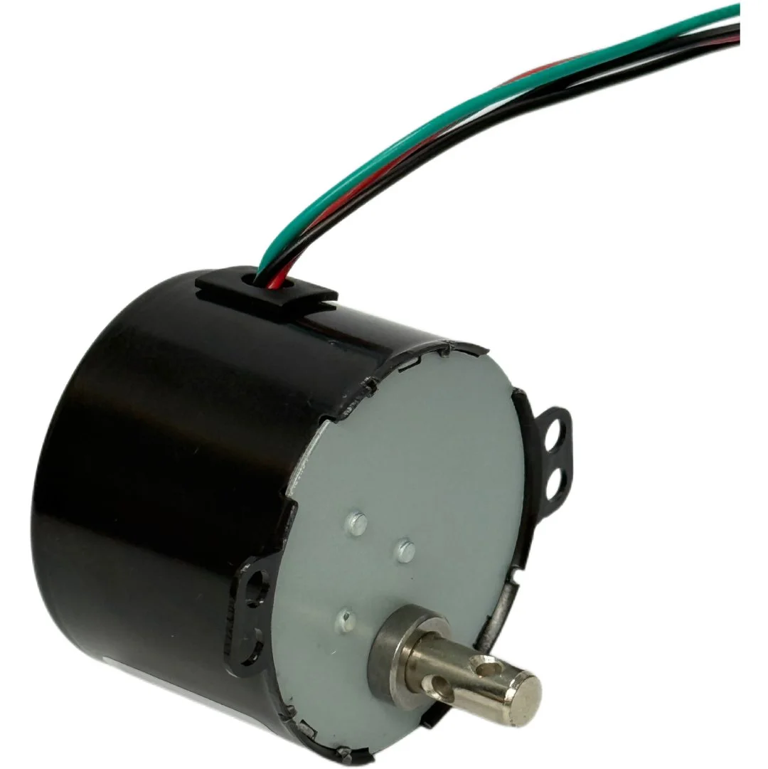
The output shaft, mounting arrangement, and any reduction gearing must suit the equipment layout. Selecting a matching configuration helps connect the motor to the driven assembly.
Timed Equipment Operation
An external control system can switch the motor according to a programmed cycle. Actual movement depends on output speed, starting behavior, load conditions, and the connected transmission.
| Parameter | Specification |
|---|---|
| Motor Model | 50KTYZ |
| Steps per Revolution | 48 (7.5°/step) |
| Speed | 1–150 rpm |
| Frequency | 50/60 Hz |
| Drive Voltage | 24–220 V |
| Coil Resistance per Phase | Customized to customer requirements |
| Insulation Resistance | ≥100 MΩ |
| Dielectric Strength | AC 500 V for 1 minute |
| Insulation Class | Class E |
| Operating Temperature | −10°C to +50°C |
| Storage Temperature | −30°C to +80°C |
| Operating Humidity | 20%–90% RH |
Potential Applications
Depending on its confirmed specifications and duty rating, the 50KTYZ Permanent Magnet Synchronous Motor may suit:
- Rotating Displays: Movement of display platforms and presentation mechanisms.
- Appliance Drives: Continuous or intermittent rotation of compatible internal components.
- Timing Mechanisms: Rotary movement associated with timed equipment functions.
- Automated Assemblies: Driving mechanisms that require a consistent operating speed.
- Instrument Devices: Rotation of components within suitably matched instrument assemblies.
Rotation Direction and Control
Confirm the rotation direction specified for the selected motor version. Equipment requiring direction changes must use a configuration that supports the intended control method.
Use the manufacturer’s wiring diagram when connecting the motor and any required external components. The motor name alone does not establish the correct wiring arrangement or capacitor requirements.
For mechanisms requiring accurate stopping positions, additional sensing or positioning components may be necessary. Synchronous running speed alone does not provide position feedback.
Mechanical Installation
Mount the motor securely and align the output shaft with the driven component. Use a compatible coupling and avoid excessive axial or radial forces.
Check clearance around the housing, shaft, terminals, and moving parts. Provide separate support where the driven assembly places loads beyond the motor’s allowable limits.
Protect electrical connections from vibration and mechanical strain. The enclosure should provide appropriate heat dissipation and environmental protection.
Application Selection
Evaluate starting torque, running load, output speed, and duty cycle together. Include friction, load inertia, and resistance changes throughout the mechanism’s movement.
An excessive load can prevent starting or cause loss of synchronism. Testing within the intended assembly helps assess startup, speed consistency, temperature rise, and performance during repeated operating cycles.

Reviews
There are no reviews yet.