
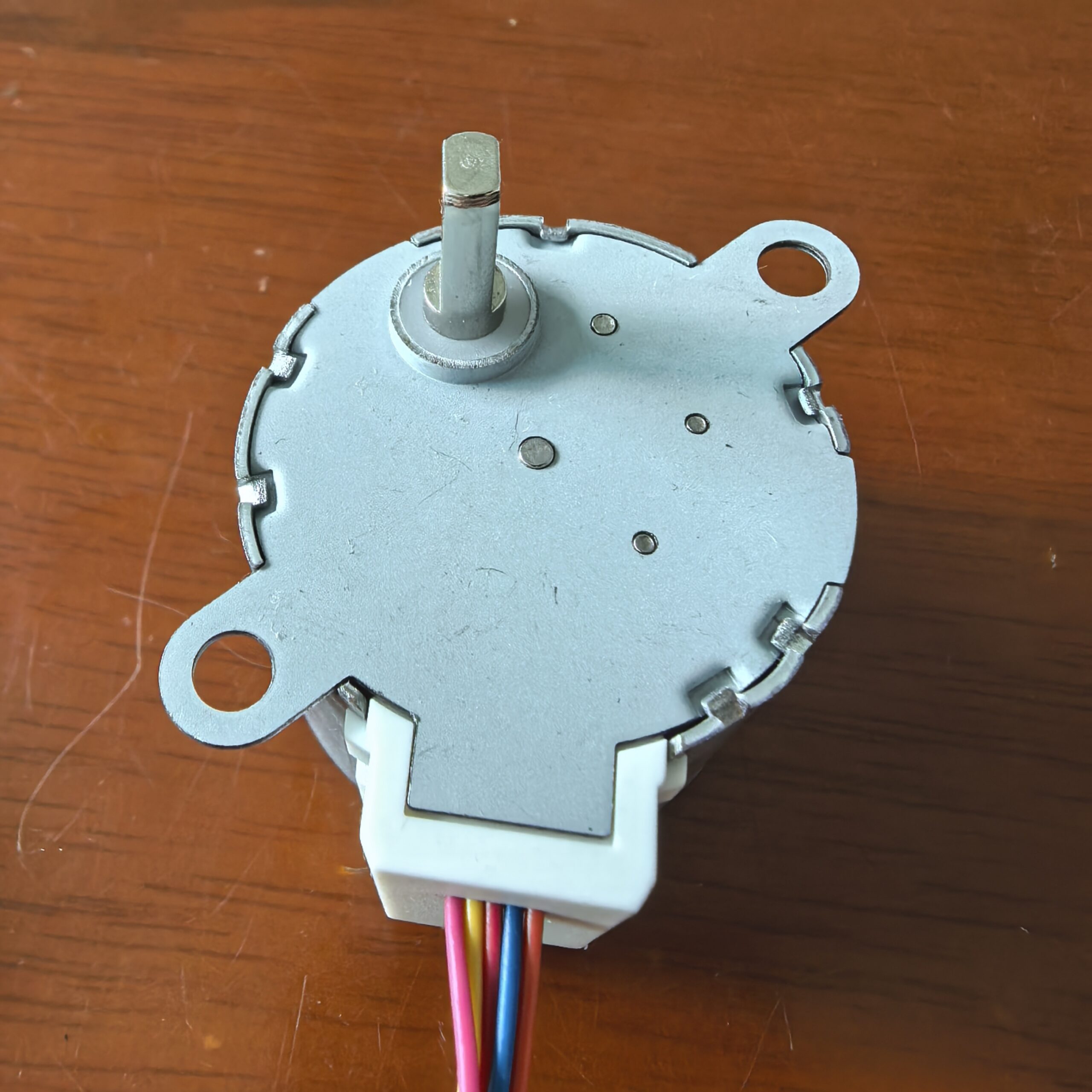
Description
Product Overview
The 35BYJ412 uses a permanent magnet rotor that responds to sequential excitation of the stator windings. The driver supplies winding power, while the controller determines the movement sequence and timing.
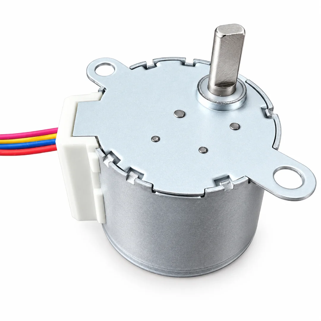
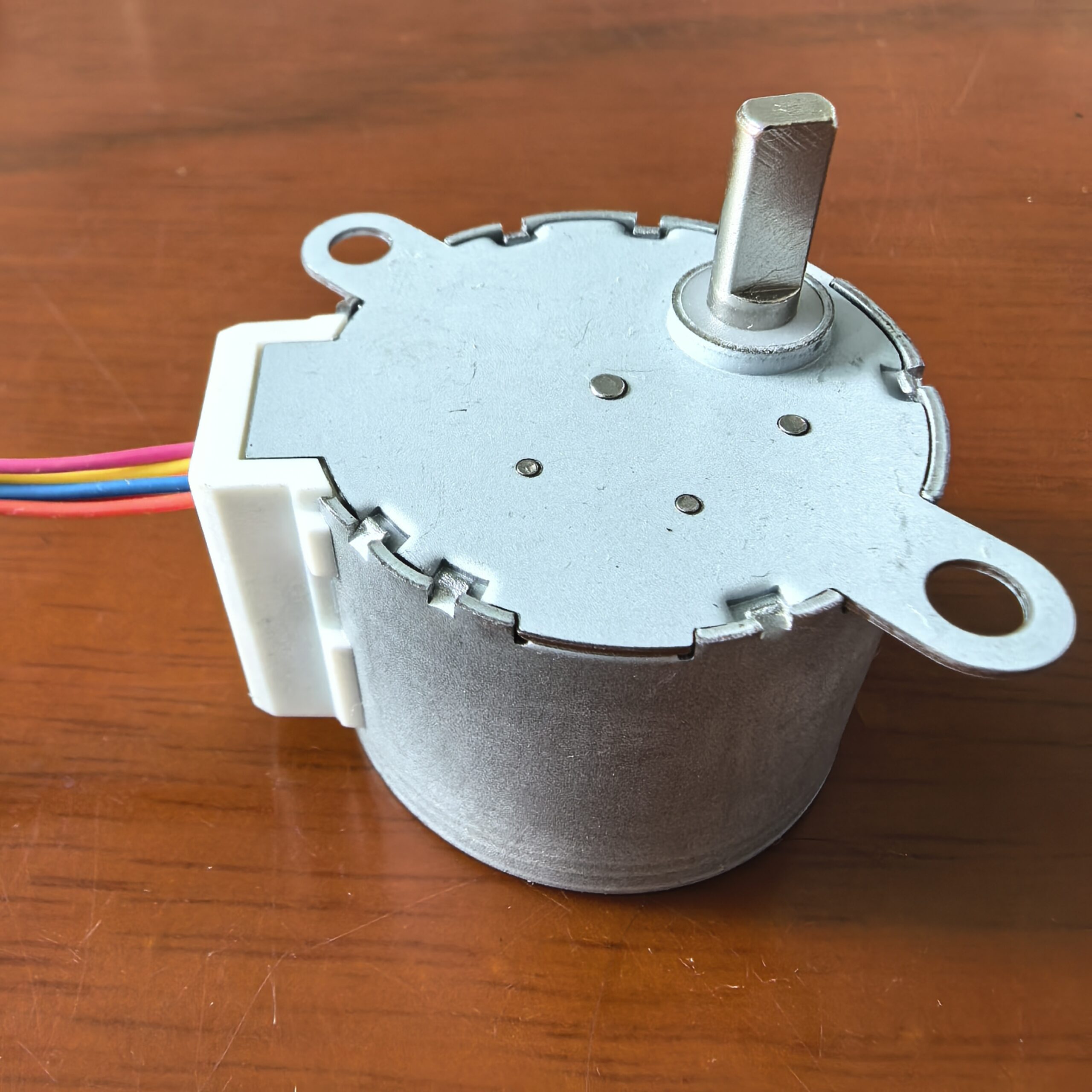
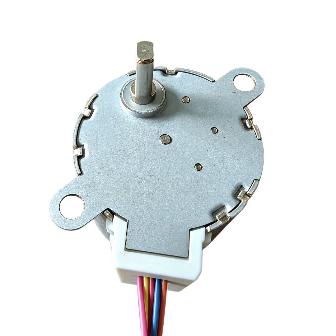
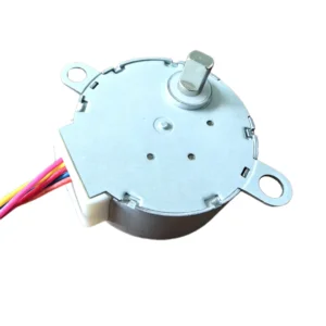
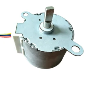
Its eccentric configuration affects the position of the output connection within the assembly. This makes the shaft location an important consideration when aligning the motor with a coupling, linkage, or driven component.
The offset arrangement does not independently create reciprocating movement. The connected mechanism determines how output rotation translates into the required equipment motion.
Key Features
Eccentric Output Arrangement
The offset output position provides an alternative to a centered shaft layout. It may help accommodate a driven component whose axis does not align with the center of the motor housing.
Permanent Magnet Construction
The rotor’s permanent magnet interacts with magnetic fields generated by the energized windings. Sequential excitation produces the stepping action used for incremental rotation.
Controlled Rotary Adjustment
A compatible control system commands movement through successive steps. This supports mechanisms that require repeated adjustment or movement between selected operating positions.
Forward and Reverse Operation
The appropriate excitation sequence enables rotation in either direction. This capability supports return cycles and mechanisms that adjust back and forth during operation.
Coordinated Motion Sequences
A suitable controller can combine movement, pauses, and direction changes with other equipment functions. Sensors or reference switches can provide additional information about the mechanism’s operating state.
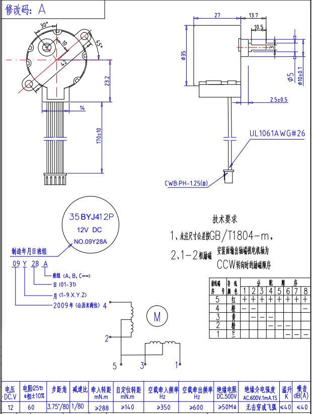
| Model | Rated Voltage (DC) | Resistance (Ω) | Starting Frequency (PPS) | Running Frequency (PPS) | Torque (mN·m) | Detent Torque (mN·m) | Step Angle | Insulation Class | Noise Level (dB) |
|---|---|---|---|---|---|---|---|---|---|
| 35BYJ412P | 12 V | 100 | ≥450 | ≥550 | ≥300 | ≥68.6 | 3.75°/80 | E | <35 |
| 35BYJ412P | 12 V | 50 | ≥450 | ≥550 | ≥147 | ≥68.6 | 3.75°/42.5 | E | <35 |
| 35BYJ412P | 12 V | 20 | ≥450 | ≥550 | ≥98 | ≥68.6 | 3.75°/24 | E | <35 |
| 35BYJ212P | 12 V | 10 | ≥450 | ≥550 | ≥49 | ≥68.6 | 3.75°/12 | E | <35 |
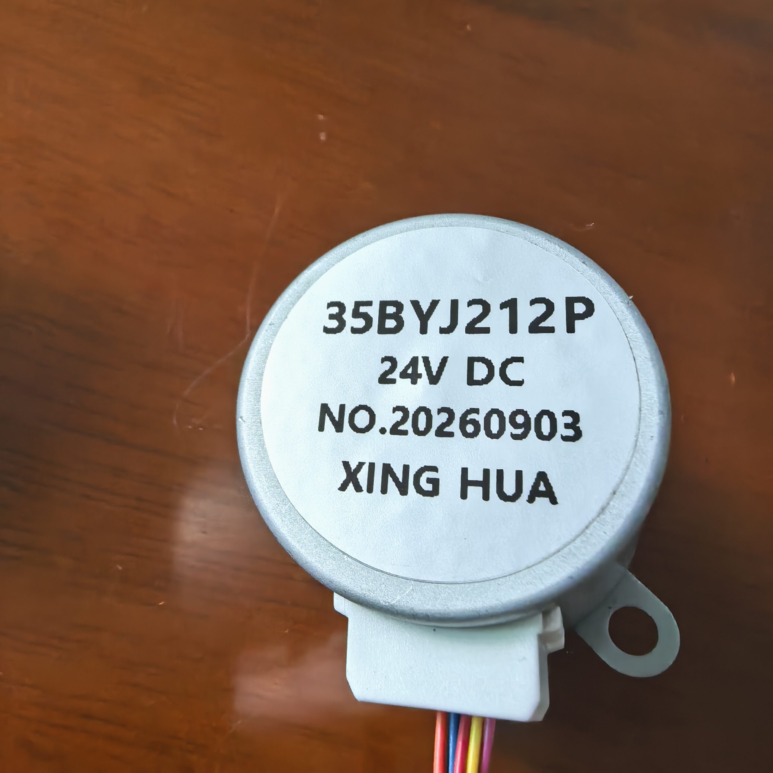
| 35BYJ212P | 24 V | 200 | ≥450 | ≥550 | ≥298 | ≥68.6 | 3.75°/80 | E | <35 |
Potential Applications
Depending on its confirmed specifications and mechanical configuration, the 35BYJ412 may suit:
- Offset Drive Assemblies: Equipment requiring an output connection away from the motor housing’s center.
- Appliance Adjustment Mechanisms: Movement of internal guides, selectors, or adjustable components.
- Linkage Actuation: Rotary input to a compatible linkage designed for the required movement.
- Instrument Mechanisms: Adjustment of movable components within a matching installation layout.
- Automated Positioning Devices: Repeated movement coordinated with programmed controller commands.
Mechanical Integration
Check the output shaft location, mounting points, shaft geometry, and surrounding clearance against the product drawing. The offset arrangement requires particular attention to alignment with the driven mechanism.
Use a compatible coupling or connection that avoids unnecessary side loading. Where a linkage introduces axial or radial forces, provide appropriate support within the assembly.
Secure the motor to a mounting structure that maintains its position during operation. Keep the wiring clear of rotating parts and moving linkages.
Driver and Control Matching
Match the driver to the motor’s winding configuration and electrical requirements. Confirm the connector assignments and excitation sequence before operation.
Choose acceleration and deceleration settings that suit the connected load. Abrupt movement can increase torque demand and cause missed steps if the assembly exceeds the motor’s operating capability.
For applications requiring position confirmation, incorporate a reference switch or suitable feedback device. Step commands alone do not verify the actual position of the driven component.
Application Evaluation
Assess the complete movement cycle, including load changes, transmission friction, and direction reversals. Mechanical backlash and linkage clearance can affect the final positioning result.
Testing within the intended equipment helps evaluate starting behavior, movement consistency, temperature rise, and mounting stability. These checks help establish a suitable combination of motor configuration, drive settings, and mechanical support.

Reviews
There are no reviews yet.